
Setting up the BIOS to speed up your computer. How to get into the BIOS? how to set up BIOS: tips How to work in BIOS

Changing BIOS settings on a PC may be required during Windows installation, after replacing system unit components, due to battery replacement, when all settings are reset to default values, etc. Understanding the purpose of the sections and menu items, you can carry out the procedure yourself, without the involvement of a specialist. Let's figure out how to configure the BIOS on a computer.
Types of BIOS
Used on computers several types of BIOS, which differ in appearance and in the location of menu items. In this case, the settings will be identical or very similar. Older computers use AWARD or AMI BIOS, modern motherboards use UEFI. The latter is a logical continuation of the development of the basic input/output system, is distinguished by the presence of a graphical interface, mouse support, the ability to select a language, and a wider range of settings.


Despite all the benefits of UEFI, users do not often upgrade their hardware, so most computers currently in use still have AWARD or AMI installed. Using the latter as an example, we will consider the setup.
How to enter BIOS
To enter the BIOS you should restart your computer. On one of the first screens, the motherboard splash screen will appear, on which the keys will be indicated that allow you to enter the system we need. Usually required press Del or F2, although there may be other variations. The surest way is to observe the information displayed on the monitor while the PC boots.
It is important to know
Using the same method, you can find out the key used to open the window in which you select priority launcher. Changing the parameter is required when installing Windows from a flash drive or disk.
Main section
Setting up BIOS on a computer begins with the Main section, which is opened by the system by default. It will work set the date and time, set hard drive parameters and view system information.

By selecting one of the presented drives and pressing the Enter key, the user will see the following settings options:
- LBA Large Mode - this parameter is more relevant to older computers, since it enabled support for drives larger than 512 MB.
- Block - allows you to deactivate the transmission of information over several simultaneously. Should be left in the "Auto" position, otherwise The speed of the hard drive will sharply decrease.
- PIO Mode - switches the drive to outdated operating mode.
- DMA Mode - activates memory access via a direct channel. To achieve maximum speed of reading and writing information, set the “Auto” parameter.
- SMART Monitoring - technology monitoring the state of the memory medium. We also leave it in automatic mode.
- 32 Bit Transfer - the parameter must be activated for information to be transferred over the PCI bus in 32-bit mode.
In point "System Information" information is provided about the BIOS version and the date of firmware creation, processor (operating speed, number of cores), (volume installed and available).
Will be useful
Some users on the “Main” tab find a parameter in the BIOS Quiet Boot. Not everyone knows what this setting is. The name of the option literally translates as “silent boot”, and means starting the OS without displaying messages about equipment testing. Instead of information from the POST procedure, the motherboard splash screen or computer logo will be displayed.
By going to the “Storage Configuration” item, you can find the following settings:

- SATA Configuration - is responsible for the SATA controller soldered into the motherboard. It can be disabled (Disable), switched to Compatible mode to work with older Windows operating systems (98, 95 and earlier) or to “Enhanced” mode to work with modern versions of operating systems.
- Configure SATA as - it is recommended to select AHCI to use modern technologies (for example, Plug-in-Play).
- Hard Disk Write Protect - Write protection of disks. The parameter must be disabled if information is intended to be added to media.
- SATA Detect Time out - time spent by the system searching for connected components. If you decrease the indicator, you will be able to speed up the OS startup, but there will be a risk that one of the disks will not be detected.
Having visited the point "JumperFree Configuration", you can set the memory clock frequency, chipset voltage, and memory bus frequency. Setting these BIOS parameters on a computer should be discussed in a separate topic. Changes must be made very carefully so as not to damage the equipment.

The item of greatest interest to the user is "USB Configuration", in which you need activate all USB ports and set the maximum data transfer speed(High Speed). All other parameters must be left in the “Auto” position.
Here you can configure the computer's power supply. The following values should be set:

- Suspend Mode - to the “Auto” position;
- ACPI APIC — enable the option (Enabled);
- ACPI 2.0 - disable the mode (set to Disabled);
- APM Configuration - leave all settings as default;
- Hardware Monitor - collected in the subsection information about the processor temperature, cooler rotation speed and voltage supplied by the power supply. You can activate the “CPU Q-fan Control” item to intelligently control the cooler speed.
This tab allows you to change your computer's boot settings. In the “Boot Device Priority” subsection it is set drive boot sequence. Sometimes the sequence has to be changed during Windows installation, when it is not possible to select a boot disk through a special window when starting the PC. In other cases, the parameters can be left unchanged, or set priority for the disk on which the operating system is located.

“Hard Disk Drivers” - in the subsection, select the disk from which you should first try to boot the OS. Configurable if There are several drives installed in the system unit.
The “Boot Setting Configuration” subsection contains the following settings:

- Quick Boot is an option in the BIOS that disables hardware tests during computer startup. If the parameter is activated, the system will boot faster, but the user will not be able to see a description of errors if they occur.
- Full Screen Logo - instead of information about the equipment, a logo will appear on the screen upon startup.
- Add On ROM Display Mode - parameter determines data display sequence about devices connected via boards that have their own BIOS.
- Bootup Num-Lock - if enabled, then after starting the PC the Num-Lock key will be in the active position.
- Wait For “F1” If Error - if an error is detected during startup testing, the user will be required to press the F1 key to further start the OS.
- Hit “DEL” Message Display - if disabled, then at startup the screen will not display a message indicating which button should be pressed to enter the BIOS.
note
Sometimes in the subsection described above you can find the option "Fast Boot" This is a setting in the BIOS, which is similar to “Quick Boot”, allowing you to speed up the loading of the OS.
Security Settings:
- Supervisor Password - makes it possible to set a password to enter the BIOS, entering which will allow you to change any parameters.
- User Password - similar, only after entering the password will be given ability to view installed settings, but not their change.
Tools and Exit section
The “Tools” tab is necessary for updating the BIOS from a floppy disk or flash drive (the “ASUS EZ Flash” item), as well as viewing information about the connected cable to the network card (the “AI NET” item).

In the “Exit” tab, you can exit settings. The following options are possible.
Hello. This article is about the BIOS setup utility, which allows the user to change basic system settings. Settings are stored in non-volatile CMOS memory and are retained when the computer is turned off.
ENTERING THE SETUP PROGRAM
To enter the BIOS setup utility, turn on the computer and immediately press the . To change additional BIOS settings, press the combination “Ctrl+F1” in the BIOS menu. The BIOS advanced settings menu will open.
CONTROL KEYS
<
?>
Go to previous menu item
<
?>
Move to next item
<
?>
Move to item on left
<
?>
Go to the item on the right
<+/PgUp>
Increase the numerical value of the setting or select another value from the list
<-/PgDn>
Decrease the numerical value of the setting or select another value from the list
REFERENCE INFORMATION
Main menu
A description of the selected setting appears at the bottom of the screen.
Settings Summary Page / Settings Pages
When you press the F1 key, a window appears with a brief hint about possible configuration options and the assignment of the corresponding keys. To close the window, click
Main menu (using the example of BIOS E2 version)
When you enter the BIOS setup menu (Award BIOS CMOS Setup Utility), the main menu opens (Fig. 1), in which you can select any of eight settings pages and two options for exiting the menu. Use the arrow keys to select the desired item. To enter the submenu, press
Fig.1: Main menu
If you can't find the setting you need, press "Ctrl+F1" and look for it in the BIOS advanced settings menu.
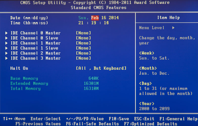
Standard CMOS Features
This page contains all standard BIOS settings.
Advanced BIOS Features
This page contains additional Award BIOS settings.
Integrated Peripherals
This page configures all built-in peripheral devices.
Power Management Setup
This page allows you to configure energy saving modes.
PnP/PCI Configurations (Configuring PnP and PCI resources)
This page allows you to configure resources for devices
PCI and PnP ISA PC Health Status (Computer health monitoring)
This page displays the measured values of temperature, voltage and fan speed.
Frequency/Voltage Control
On this page you can change the clock frequency and processor frequency multiplier.
To achieve maximum performance, set the “Top Performance” item to “Enabled”.
Load Fail-Safe Defaults
Secure default settings ensure system functionality.
Load Optimized Defaults
The default optimized settings provide optimal system performance.
Set Supervisor password
On this page you can set, change or remove your password. This option allows you to restrict access to the system and BIOS settings, or only to the BIOS settings.
Set User password
On this page you can set, change or remove a password that allows you to restrict access to the system.
Save & Exit Setup
Saving settings in CMOS and exiting the program.
Exit Without Saving
Cancels all changes made and exits the setup program.
Standard CMOS Features
Fig.2: Standard BIOS settings
Date
Date format:<день недели>, <месяц>, <число>, <год>.
Day of the week - the day of the week is determined by the BIOS based on the entered date; it cannot be changed directly.
Month - the name of the month, from January to December.
Number - day of the month, from 1 to 31 (or the maximum number of days in the month).
Year - year, from 1999 to 2098.
Time
Time format:<часы> <минуты> <секунды>. Time is entered in 24-hour format, for example, 1 o'clock in the afternoon is written as 13:00:00.
IDE Primary Master, Slave / IDE Secondary Master, Slave (IDE Disk Drives)
This section defines the parameters of the disk drives installed in the computer (from C to F). There are two options for setting parameters: automatically and manually. When defining manually, the drive parameters are set by the user, and in automatic mode, the parameters are determined by the system. Please note that the information you enter must match your drive type.
If you enter incorrect information, the disk will not work properly. If you select the User Type option, you will need to fill out the items below. Enter data using the keyboard and press
CYLS - Number of cylinders
HEADS - Number of heads
PRECOMP - Precompensation when recording
LANDZONE - Head parking zone
SECTORS - Number of sectors
If one of the hard drives is not installed, select NONE and press
Drive A / Drive B (Floppy drives)
This section specifies the types of floppy drives A and B installed in the computer. -
None - Floppy drive is not installed
360K, 5.25 in. Standard 5.25-inch PC-type floppy drive with 360 KB capacity
1.2M, 5.25in. 5.25" high-density AT floppy drive with 1.2 MB capacity
(3.5-inch drive if mode 3 support is enabled).
720K, 3.5 in. 3.5-inch floppy drive with double-sided recording; capacity 720 KB
1.44M, 3.5in. 3.5-inch floppy drive with double-sided recording; capacity 1.44 MB
2.88M, 3.5in. 3.5-inch floppy drive with double-sided recording; capacity 2.88 MB.
Floppy 3 Mode Support (for Japan Area)
Disabled Regular floppy drive. (Default setting)
Drive A Floppy drive A supports mode 3.
Drive B Floppy drive B supports mode 3.
Both floppy drives A and B support mode 3.
Halt on
This setting determines which errors will stop the system boot when detected.
NO Errors The system will continue to boot despite any errors. Error messages are displayed on the screen.
All Errors Boot will be aborted if the BIOS detects any error.
All, But Keyboard The download will be aborted on any error other than a keyboard failure. (Default setting)
Ail, But Diskette The boot will abort on any error except a floppy drive failure.
All, But Disk/Key Boot will abort on any error except keyboard or disk failure.
Memory
This item displays the memory sizes determined by the BIOS during system self-test. You cannot change these values manually.
Base Memory
During the automatic self-test, the BIOS determines the amount of base (or regular) memory installed in the system.
If the system board has 512 KB of memory installed, the value is 512 K, and if the motherboard has 640 KB or more memory installed, the value is 640 K.
Extended Memory
During the automatic self-test, the BIOS determines the size of extended memory installed on the system. Extended memory is RAM with addresses above 1 MB in the CPU's addressing system.
Advanced BIOS Features
Fig.Z: Additional BIOS settings
First / Second / Third Boot Device
(First/second/third boot device)
Floppy Loading from a floppy disk.
LS120 Boot from LS120 drive.
HDD-0-3 Boot from hard disk 0 to 3.
SCSI Boot from a SCSI device. Boot from a ZIP drive.
USB-FDD Boot from a USB floppy drive.
USB-ZIP Boot from a USB ZIP device.
USB-CDROM Boot from a USB CD-ROM.
USB-HDD Boot from a USB hard drive.
LAN Download via local network.
Boot Up Floppy Seek (Detecting the type of floppy drive at boot)
During the system self-test, the BIOS determines whether the floppy drive is 40-track or 80-track. The 360 KB drive is a 40-track drive, while the 720 KB, 1.2 MB, and 1.44 MB drives are 80-track.
Enabled BIOS determines the drive type - 40- or 80-track. Keep in mind that the BIOS does not differentiate between 720 KB, 1.2 MB, and 1.44 MB drives because they are all 80-track drives.
Disabled BIOS will not detect the drive type. When installing a 360 KB drive, no message is displayed on the screen. (Default setting)
Password Check
System If you do not enter the correct password when prompted by the system, the computer will not boot and access to the settings pages will be denied.
Setup If you do not enter the correct password when prompted by the system, the computer will boot, but access to the settings pages will be blocked. (Default setting)
CPU Hyper-Threading
Disabled Hyper Threading mode is disabled.
Enabled Hyper Threading mode is enabled. Please note that this feature is only implemented if the operating system supports a multiprocessor configuration. (Default setting)
DRAM Data Integrity Mode
The option allows you to set the error control mode in RAM if ECC type memory is used.
ECC ECC mode is enabled.
Non-ECC ECC mode is not used. (Default setting)
Init Display First (The order in which video adapters are activated)
AGP Activate the AGP video adapter first. (Default setting)
PCI Activate the PCI video adapter first.
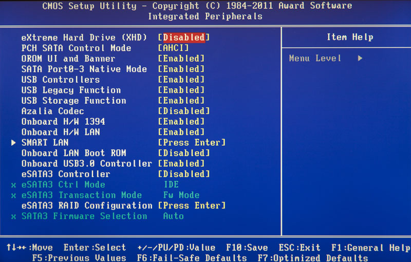
Integrated Peripherals
Figure 4: Embedded peripherals
On-Chip Primary PCI IDE (Built-in controller 1 channel IDE)
Enabled Built-in 1 channel IDE controller is enabled. (Default setting)
Disabled The built-in IDE channel 1 controller is disabled.
On-Chip Secondary PCI IDE (Built-in controller 2 channels IDE)
Enabled Built-in 2 channel IDE controller is enabled. (Default setting)
Disabled The built-in IDE channel 2 controller is disabled.
IDE1 Conductor Cable (Type of cable connected to IDE1)
ATA66/100 A cable of type ATA66/100 is connected to IDE1. (Make sure your IDE device and cable support ATA66/100 mode.)
ATAZZ A cable of type ATAZZ is connected to IDE1. (Make sure your IDE device and cable support ATAZZ mode.)
IDE2 Conductor Cable (Type of cable connected to ШЭ2)
Auto Automatically detected by BIOS. (Default setting)
ATA66/100/133 A cable of type ATA66/100 is connected to IDE2. (Make sure your IDE device and cable support ATA66/100 mode.)
ATAZZ A cable of type ATAZZ is connected to IDE2. (Make sure your IDE device and cable support ATAZZ mode.)
USB Controller
If you are not using the built-in USB controller, disable this option here.
Enabled The USB controller is enabled. (Default setting)
Disabled The USB controller is disabled.
USB Keyboard Support
When connecting a USB keyboard, set this item to “Enabled”.
Enabled USB keyboard support is enabled.
Disabled USB keyboard support is disabled. (Default setting)
USB Mouse Support
When connecting a USB mouse, set this item to “Enabled”.
Enabled USB mouse support is enabled.
Disabled USB mouse support is disabled. (Default setting)
AC97 Audio (AC'97 Audio Controller)
Auto Built-in audio controller AC'97 is enabled. (Default setting)
Disabled Built-in audio controller AC'97 is disabled.
Onboard H/W LAN (Built-in network controller)
Enable The built-in network controller is enabled. (Default setting)
Disable The built-in network controller is disabled.
Onboard LAN Boot ROM
Using the embedded network controller ROM to boot the system.
Enable The function is enabled.
Disable The function is disabled. (Default setting)
Onboard Serial Port 1
Auto BIOS sets port 1 address automatically.
3F8/IRQ4 Enable the built-in serial port 1 by assigning it the address 3F8.(Default setting)
2F8/IRQ3 Enable the built-in serial port 1 by assigning it the address 2F8.
3E8/IRQ4 Enable built-in serial port 1, assigning it the address ZE8.
2E8/IRQ3 Enable built-in serial port 1, assigning it the address 2E8.
Disabled Disable the built-in serial port 1.
Onboard Serial Port 2
Auto BIOS sets port 2 address automatically.
3F8/IRQ4 Enable the built-in serial port 2 by assigning it the address 3F8.
2F8/IRQ3 Enable the built-in serial port 2 by assigning it the address 2F8. (Default setting)
3E8/IRQ4 Enable the built-in serial port 2, assigning it the address ZE8.
2E8/IRQ3 Enable built-in serial port 2, assigning it the address 2E8.
Disabled Disable the built-in serial port 2.
Onboard Parallel port
378/IRQ7 Enable the built-in LPT port by assigning it address 378 and assigning the IRQ7 interrupt. (Default setting)
278/IRQ5 Enable the built-in LPT port by assigning it address 278 and assigning the IRQ5 interrupt.
Disabled Disable the built-in LPT port.
3BC/IRQ7 Enable the built-in LPT port by assigning it the DS address and assigning the IRQ7 interrupt.
Parallel Port Mode
SPP The parallel port is operating normally. (Default setting)
EPP Parallel port operates in Enhanced Parallel Port mode.
ECP Parallel port operates in Extended Capabilities Port mode.
ECP + EPP The parallel port operates in ECP and EPP modes.
ECP Mode Use DMA
3 ECP mode uses DMA channel 3. (Default setting)
1 ECP mode uses DMA channel 1.
Game Port Address
201 Set the game port address to 201. (Default setting)
209 Set the game port address to 209.
Disabled Disable the function.
Midi Port Address
290 Set the MIDI port address to 290.
300 Set the MIDI port address to 300.
330 Set the MIDI port address to 330. (Default setting)
Disabled Disable the function.
Midi Port IRQ (MIDI Port Interrupt)
5 Assign IRQ 5 to the MIDI port.
10 Assign IRQ 10 to the MIDI port. (Default setting)
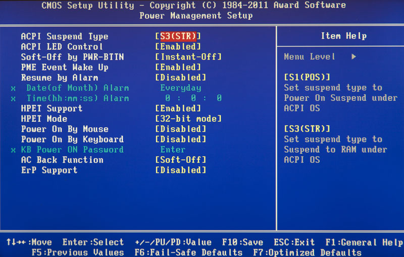
Power Management Setup
Figure 5: Power Management Settings
ACPI Suspend Type
S1(POS) Set S1 standby mode. (Default setting)
S3(STR) Set S3 standby mode.
Power LED in SI state
Blinking In standby mode (S1), the power indicator blinks. (Default setting)
Dual/OFF In standby mode (S1):
a. If a single-color indicator is used, it goes out in S1 mode.
b. If a two-color indicator is used, it changes color in S1 mode.
Soft-offby PWR BTTN (Computer soft-off)
Instant-off When you press the power button, the computer turns off immediately. (Default setting)
Delay 4 Sec. To turn off the computer, hold down the power button for 4 seconds. When you press the button briefly, the system goes into standby mode.
PME Event Wake Up
Disabled The PME event wake-up function is disabled.
ModemRingOn
Disabled The modem/LAN wake-up feature is disabled.
Enabled The function is enabled. (Default setting)
Resume by Alarm
In the Resume by Alarm item, you can set the date and time the computer turns on.
Enabled The function of turning on the computer at a specified time is enabled.
If the feature is enabled, set the following values:
Date (of Month) Alarm: Day of the month, 1-31
Time (hh: mm: ss) Alarm: Time (hh: mm: cc): (0-23): (0-59): (0-59)
Power On By Mouse
Disabled The function is disabled. (Default setting)
Double Click Wake up your computer when you double click the mouse.
Power On By Keyboard
Password To turn on the computer, you must enter a password of 1 to 5 characters.
Disabled The function is disabled. (Default setting)
Keyboard 98 If your keyboard has a power button, pressing it turns on the computer.
KB Power ON Password (Setting a password to turn on the computer from the keyboard)
Enter Enter a password (1 to 5 alphanumeric characters) and press Enter.
AC Back Function (Computer behavior after a temporary power failure)
Memory When power is restored, the computer returns to the state it was in before the power was lost.
Soft-Off The computer remains off after power is turned on. (Default setting)
Full-On After power is restored, the computer turns on.
PnP/PCI Configurations
Fig.6: Configuring PnP/PCI devices
PCI l/PCI5 IRQ Assignment
Auto Automatic interrupt assignment for PCI 1/5 devices. (Default setting)
3, 4, 5, 7, 9, 10, 11, 12, 15 Assignment for PCI 1/5 devices IRQ 3, 4, 5, 7, 9, 10, 11, 12, 15.
PCI2 IRQ Assignment
Auto Automatically assigns an interrupt to the PCI 2 device. (Default setting)
3, 4, 5, 7, 9, 10, 11, 12, 15 Assignment for PCI 2 device IRQ 3, 4, 5, 7, 9, 10, 11, 12, 15.
ROZ IRQ Assignment (Interrupt assignment for PCI 3)
Auto Automatically assigns an interrupt to the PCI 3 device. (Default setting)
3, 4, 5, 7, 9, 10, 11, 12, 15 Assignment for PCI 3 device IRQ 3, 4, 5, 7, 9, 10, 11, 12, 15.
PCI 4 IRQ Assignment
Auto Automatically assigns an interrupt to the PCI 4 device. (Default setting)
3, 4, 5, 7, 9, 10, 11, 12, 15 Assignment for PCI 4 device IRQ 3, 4, 5, 7, 9, 10, 11, 12, 15.
PC Health Status
Fig.7: Computer status monitoring
Reset Case Open Status
Case Opened
If the computer case has not been opened, “Case Opened” will display “No.” If the case has been opened, “Case Opened” will display “Yes.”
To reset the sensor readings, set the “Reset Case Open Status” item to “Enabled” and exit the BIOS saving the settings. The computer will restart.
Current Voltage (V) Vcore / VCC18 / +3.3 V / +5V / +12V (Current system voltage values)
This item displays the automatically measured main voltages in the system.
Current CPU Temperature
This item displays the measured processor temperature.
Current CPU/SYSTEM FAN Speed (RPM)
This item displays the measured rotation speed of the processor and case fans.
CPU Warning Temperature
Disabled The processor temperature is not monitored. (Default setting)
60°C / 140°F A warning is issued when the temperature exceeds 60°C.
70°C / 158°F A warning is issued when the temperature exceeds 70°C.
80°C / 176°F A warning is issued when the temperature exceeds 80°C.
90°C / 194°F A warning is issued when the temperature exceeds 90°C.
CPU FAN Fail Warning
Disabled The function is disabled. (Default setting)
SYSTEM FAN Fail Warning
Disabled The function is disabled. (Default setting)
Enabled When the fan stops, a warning is issued.
Frequency/Voltage Control
Fig.8: Frequency/voltage adjustment
CPU Clock Ratio
If the processor frequency multiplier is fixed, this option is not available in the menu. - 10X - 24X The value is set depending on the processor clock frequency.
CPU Host Clock Control
Note: If the system freezes before loading the BIOS setup utility, wait 20 seconds. After this time, the system will reboot. When rebooting, the processor base frequency will be set to the default value.
Disabled Disable the function. (Default setting)
Enabled Enable the processor base frequency control function.
CPU Host Frequency
100MHz - 355MHz Set the base processor frequency value from 100 to 355 MHz.
PCI/AGP Fixed
To adjust AGP/PCI clock frequencies, select 33/66, 38/76, 43/86 or Disabled.
Host/DRAM Clock Ratio
Attention! If the value in this item is set incorrectly, the computer will not be able to boot. In this case, you should reset the BIOS settings.
2.0 Memory frequency = Base frequency X 2.0.
2.66 Memory frequency = Base frequency X 2.66.
Auto The frequency is set according to the SPD data of the memory module. (Default value)
Memory Frequency (Mhz)
The value is determined by the base frequency of the processor.
PCI/AGP Frequency (Mhz)
Frequencies are set depending on the value of the CPU Host Frequency or PCI/AGP Divider option.
CPU Voltage Control
The processor supply voltage can be increased by 5.0% to 10.0%. (Default: nominal)
DIMM OverVoltage Control
Normal The memory supply voltage is equal to the nominal voltage. (Default value)
+0.1V Memory supply voltage increased by 0.1 V.
+0.2V Memory supply voltage increased by 0.2 V.
+0.3V Memory supply voltage increased by 0.3 V.
For advanced users only! Incorrect installation may damage your computer!
AGP OverVoltage Control
Normal The video adapter's supply voltage is equal to the nominal voltage. (Default value)
+0.1V The video adapter supply voltage is increased by 0.1 V.
+0.2V The video adapter supply voltage is increased by 0.2 V.
+0.3V The video adapter supply voltage is increased by 0.3 V.
For advanced users only! Incorrect installation may damage your computer!
Top Performance
Fig.9: Maximum performance
Top Performance
To achieve the best system performance, set the “Top Performance” item to “Enabled”.
Disabled The function is disabled. (Default setting)
Enabled Maximum performance mode.
Enabling Maximum Performance mode increases the speed of your hardware components. System operation in this mode is influenced by both hardware and software configurations. For example, the same hardware configuration may work well under Windows NT, but not work under Windows XP. Therefore, if there are problems with the reliability or stability of the system, we recommend disabling this option.
Load Fail-Safe Defaults
Figure 10: Setting secure defaults
Load Fail-Safe Defaults
Safe default settings are system parameter values that are the most secure from the point of view of system performance, but provide minimal performance.
Load Optimized Defaults
When you select this menu item, the default BIOS and chipset settings are loaded, automatically detected by the system.
Set Supervisor/User Password
Fig.12: Setting a password
When you select this menu item, a password prompt will appear in the center of the screen.
Enter a password of no more than 8 characters and press
To cancel your password, when prompted to enter a new password, click
The BIOS settings menu allows you to set two different passwords: the administrator password (SUPERVISOR PASSWORD) and the user password (USER PASSWORD). If no passwords are set, any user can access BIOS settings. When setting a password, you must enter the administrator password to access all BIOS settings, and the user password to access only basic settings.
If you select the “System” option in the BIOS advanced settings menu in the “Password Check” item, the system will prompt you for a password every time you boot the computer or try to enter the BIOS settings menu.
If you select “Setup” in the BIOS advanced settings menu under “Password Check”, the system will only ask for a password when you try to enter the BIOS settings menu.
Save & Exit Setup
Fig.13: Saving settings and exit
To save your changes and exit the settings menu, press “Y”. To return to the settings menu, press “N”.
Exit Without Saving
Fig. 14: Exit without saving changes
To exit the BIOS settings menu without saving the changes made, press “Y”. To return to the BIOS settings menu, press "N".
How to set the system date and time? How do I boot my computer from a CD or flash drive? You will get answers to these and other common questions by becoming familiar with the basic BIOS settings and how to edit them.
Introduction
If you do not yet know what a BIOS is and what this firmware is needed for, then we advise you to read our previous material, which talks about how a computer boots up and what role the “basic input system” plays in this process conclusion." In the same article, we will get acquainted with the BIOS setup program, which is most often called BIOS (CMOS) Setup Utility.
By the way, in most cases, users use abbreviated names for this program, calling it BIOS Setup or simply BIOS. For example, you can often hear expressions such as “go into the BIOS” or “open the BIOS,” which is somewhat incorrect, since in both cases we are talking about entering the BIOS Setup program, which is only part of the BIOS.
In most cases, BIOS Setup is used by ordinary users only to set the system time and date or select boot devices. But in fact, this program can have a lot of possibilities. Using it, you can control the operation of the processor, RAM, chipset and other important PC components, monitor the temperature conditions of devices and perform many other useful actions.
Entering BIOS (CMOS) Setup Utility
In order to launch the BIOS setup program, you must press a certain key or a combination of keys during the initial PC testing procedure. In the vast majority of cases, on desktop computers, the Del key is used to enter BIOS Setup, or less often F1 or F2. In laptops, on the contrary, it is the function keys (F1, F2, F11, F12) that are most often used for these purposes.

You can find out exactly which keys are used to launch BIOS Setup from the instructions for your computer or motherboard. Also, in some cases, during the POST procedure, a hint is displayed on the monitor screen indicating which key must be pressed to enter the settings.

True, in modern computers and laptops, on-screen prompts are becoming less and less common, but in any case, a search query on the Internet will always help you find the right key.
In addition to the need to know the right key to get into BIOS Setup, it is equally important to choose the right moment to press it. In order not to be late, it is better to press the enter key repeatedly immediately after the PC starts booting. In most cases, this method is guaranteed to launch BIOS settings.
BIOS Interface (CMOS) Setup Utility
The Bios Setup program has a text interface without any design tricks and is controlled exclusively using the keyboard. This is explained by the fact that the graphical shell of this application has remained virtually unchanged since the 80s, so everything looks very simple and ascetic.
In general, the BIOS Setup interface comes in two types: with the main menu arranged in two columns or horizontally. You can understand which type is in front of you immediately after entering the program and opening its main window.

In the first case, you will see a list of sections arranged in two columns on a blue background. This option is typical for BIOS versions developed by Phoenix Technologies (AwardBIOS, Award Modular BIOS, Award WorkstationBIOS). They are traditionally used in their motherboards by manufacturers such as MSI, Gigabyte, Foxconn, ECS and others.

In the second case, a window with a gray background will appear in front of you, in which a menu with the main sections will be placed on top of the screen, in the form of a blue horizontal strip. This interface is usually characteristic of American Megatrends BIOS (AMIBIOS, Aptio AMIBIOS), used in motherboards from ASUS, Intel, ASRock and some others.
Despite such differences in the interface of these two options, all sections of BIOS Setup have a similar presentation. To verify this, let's look at the structure of the program windows in both cases.
At the top of the screen you will always find the name of the current section (in the case of a horizontal menu, the name is highlighted) or subsection.

The main part of the screen is occupied by an area containing a list of subsections (indicated by triangular arrows) and parameters of the selected section. To the right of the parameter names are their values. It is worth considering that if a parameter is highlighted in a pale color (blue or light gray), then it either has a “read-only” status and is for informational purposes only, or to edit it it is necessary to change another parameter associated with it.

The right side of the screen is usually occupied by a column that displays brief reference information on the selected parameter or subsection, as well as tips on possible actions and use of control keys (American Megatrends). In a BIOS setup program with a blue background, a hint for using the function keys is usually located at the bottom of the screen.
As you can see, despite the different color schemes and slight differences in the location of work elements on the screen, in essence both interfaces are very similar and present information to users in almost the same way. That is why the techniques for working with BIOS parameters are almost the same in both cases.
To navigate through the menu and select the desired parameters, subsections or sections, use the arrow keys, and to open them, use the Enter key. The “ESC” key is responsible for returning to the previous screen and exiting the current settings. Also, using this key, you can exit BIOS Setup without making changes to the settings by pressing it in the main menu. In addition, the functions of the “F1” key, which calls up help, and “F10,” which initializes the exit from BIOS Setup from anywhere in the program and saves the changes made, are unchanged. The "PageUP"/"PageDown" or "+"/"-" keys are traditionally used to sequentially cycle through the available values of changeable parameters.
In addition to the above keys, other function keys (“F2” - “F9”, “F11”, “F12”) can be used to work with BIOS settings, but their purpose may differ depending on the board model and its manufacturer. However, it is not difficult to understand what each of them is responsible for. It is enough to refer to the prompts that appear on the screen or look through the manual for the motherboard.
Main sectionsBIOSSetupwith columnar main menu (blue background)
Each motherboard model in many cases has its own unique set of customizable parameters, but the names and thematic focus of the main sections of BIOS Setup usually remain unchanged.
Standard CMOS Futures
This section contains the basic (standard) computer settings, which include: setting the system date and time ( Date, Time), disk drive parameters ( IDE Channel), as well as various information about the system (information about the installed processor, amount of RAM, and others).
By the way, setting the date and time for most users is one of the most key reasons for visiting BIOS Setup.
Advanced BIOS Features
This section contains advanced BIOS settings. The most common of them include:
- CPU Cache Management
- Parameters related to the nuances of booting a computer. For example, here you can enable/disable NumLock mode, accelerated boot mode ( Quick Boot), as well as displaying the logo of the board manufacturer during the self-test procedure ( Full Screen LOGO Show).
- Selecting the boot device polling sequence ( First/Second/Third Boot Device). Another most requested feature in BIOS Setup, along with setting the date and time.
- Enable/disable S.M.A.R.T. hard drive self-monitoring technology.

It is worth considering that depending on the board model and BIOS modification, the set of settings in this section may vary.
Advanced Chipset Features
This section describes the settings of the chipset installed on the motherboard, as a result of which the set of parameters here directly depends on its type and modification. In most cases, options are collected here that are responsible for the operation of RAM (adjusting frequency and timings), the data exchange bus between the processor and RAM, the AGP/PCI-E graphics bus and the video adapter.

It should be noted that in some situations, it is by changing the parameters of this section that you can increase the speed of your computer or, as they say, overclock. However, recently, options responsible for increasing the speed of a PC are most often placed by manufacturers in a separate specialized section of the BIOS.
Integrated Peripherals
This section contains parameters responsible for the operation of peripheral devices integrated into the motherboard, such as: hard drive controllers, USB ports, sound and network adapters, and others.
For example, here you can enable/disable the built-in sound card, support for USB input devices, or select RAID mode to create an array of hard drives.
Here are collected options that are responsible for the power supply and energy saving modes of the computer. Almost all modern computers allow power management directly from the operating system, but this requires BIOS support for specialized ACPI standards, the mode and functions of which are regulated in this section.
Also here you can specify what actions should occur when you press the power button, set the conditions for turning on the PC and its transition to reduced energy consumption or exit from hibernation.
PnP/PCI Configurations
This section contains control parameters for Plug and Play technology, which is responsible for distributing resources between PC devices and their quick configuration, as well as settings for the PCI bus. As a rule, these functions are successfully performed by the system and do not require manual intervention. Therefore, in modern computers this section may not be present at all.
PC Health Status ( H/ W Monitor)
Modern motherboards are always equipped with sensors that monitor the operating temperatures and voltages of the main devices, as well as the rotation speed of the cooling system fans. All their indicators are displayed in this section.

In addition, in PC Health Status you can control fan operating modes and configure alert options in case of overheating, cooler stoppage, or opening of the case cover.
Frequency/ Voltage Control
This section contains parameters responsible for setting operating frequencies and voltage values for the processor, RAM, video card and other devices. By default, all frequencies and voltages have recommended values and are adjusted automatically, which guarantees reliable operation of the system.

However, the value of some parameters in this section can be changed manually. This makes it possible to overclock the processor, memory and other components, forcing them to operate at higher frequencies. You just need to remember that, on the one hand, overclocking allows you to increase the overall performance of the system, and on the other hand, it can cause malfunctions in the PC and cause failure of the overclocked hardware (for example, when setting too high voltage values). So you have to be very careful here.

It is worth noting that many large motherboard manufacturers include options for setting frequencies and voltages in a special section with an original name, for example MB Intelligent Tweaker (M.I.T.) or Cell Menu .
Load Fail- Safe Defaults
This is not a section, but a command that resets all BIOS settings to default values, which guarantee stable operation of the entire system. After selecting this item, a window will open in front of you in which you will need to confirm the reset by pressing the “Y” key.

A command that sets the BIOS settings values in such a way as to ensure optimal computer performance while maintaining the stability of all its components. However, the parameters that are automatically changed depend on the motherboard model and may vary.

However, please note that such optimization of settings in some cases may lead to unstable operation of the system due to incompatibility of the installed equipment. Then you should return to the default settings using the command Load Fail-Safe Defaults and try to configure the necessary parameters manually.
Set Supervisor Password
A command that allows you to set, remove or change the administrative password, which is used for full access to all BIOS settings, as well as when booting the PC.
Set User Password
A command that sets a user password that allows access to view BIOS parameter values. That is, most of the settings will be closed for editing. This password can also be used when booting the computer.
Main sectionsBIOSSetupwith horizontal main menu (gray background)
As we have already noted, the BIOS setup interface exists in two main versions, which differ not only in the external design and location of the main menu, but also in the layout of the parameters by section. So now let's get acquainted with the second type of interface, which is used by such motherboard market leaders as ASUS or AsRock.
Main
Based on the name, according to the developers, this section contains the main BIOS settings, which include time and date, parameters of installed disk drives and general system information (BIOS version, processor model, amount of installed memory). Thus, Main is almost a complete analogue of the section already familiar to us .
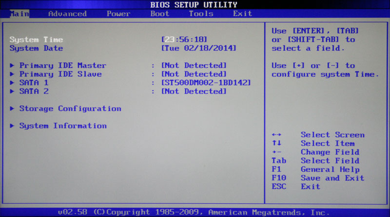
As you probably already guessed, the most popular option in this section is setting the system date and time.
Advanced
As a rule, this section has the largest number of options for configuring components and PCs and includes several significant subsections at once. Here are the parameters responsible for the operation of the central processor ( CPU Configuration), RAM, video adapter, chipset ( Chipset), PCI data bus and Plug and Play technology ( PnP/PCI Configuration, PCI PnP), embedded peripherals ( Onboard Device Configuration), USB ports ( USB Configuration) and other equipment.

Also in this section you can find overclocking options that allow you to manually set the frequencies and voltages of the processor, memory, and PCI-E bus. In some cases, users can additionally adjust RAM delays (timings/latency). In many motherboard models, the parameters responsible for overclocking are placed in a separate subsection (for example, JumperFreeConfiguration) or even a separate section of the main menu ( A.I.Tweaker, Overclocking or ExtremeTweaker).
Due to the fairly large set of components and variety of parameters, section Advanced has practically no unified structure. Depending on the board model and BIOS developer, the number of subsections/settings and their names can vary greatly. After all, if you compare it with the BIOS Setup version, which has a blue background, it turns out that in the section Advanced The contents of five sections are collected at once: Advanced BIOS Features, Advanced Chipset Features, Integrated Peripherals, Frequency/Voltage Control And PnP/PCI Configurations.
Power
This section is identical in content and essence to sections And PC Health Status (H/W Monitor).

Here are the parameters responsible for power supply and energy saving of the PC, monitoring the operating temperatures and voltages of its main components, as well as controlling fan speeds.
Boot
Already from the name it is clear that this section is responsible for configuring the computer boot parameters. This is where the settings for determining the polling sequence of boot devices and enabling/disabling the “Num Lock” key (subsection Boot Settings Configuration).

In many cases the section Boot includes subsection Security, containing commands for setting, removing or changing administrative and user passwords. In some versions of BIOS Setup, password management parameters can be placed in a separate section of the same name.
Tools
Most motherboards from the popular manufacturer ASUS contain an additional section that contains auxiliary tools for updating the BIOS ( EZ Flash 2), disable/enable mini-OS on the Linux kernel ( Express Gate), creating custom BIOS settings profiles ( O.C. Profile), as well as checking the network cable connection while the PC is booting ( AINET 2).
Exit
This section is responsible for exiting the BIOS settings menu and combines the following commands:
- Exit & Save Changes- provides exit from the program with saving all the changes you have made.
- Exit & Discard Changes- exits the program without saving all changes made.
- Load Setup Defaults- returns BIOS settings to default values (factory reset).
- Discard Changes- canceling changes made without exiting the program.

After selecting any of the above commands, a window will appear in front of you in which you need to confirm its execution by pressing the “Y” key and then “Enter”
Setting the time and date
When you turn on a new computer for the first time, it is better to immediately take care of setting the correct system time and date values in the BIOS, thereby setting a basic reference point for both the operating system and software that can function without an installed OS.
To get into the BIOS settings menu, immediately after the computer starts booting, press the desired key (usually “Del” or “F2”). After the main BIOS Setup menu appears in front of you, to achieve the task, we perform several simple manipulations.
BIOSSetup with blue background
Use the arrow keys to move the cursor to the section and press “Enter”. Often this section comes first and there is no need to move anything anywhere, but there are exceptions.

In the window that opens with options, at the top we find the two parameters we need - Date and Time. Use the arrows to move between parameter values. To set values, you can use either the “+”/“PgUp” or “-”/“PgDn” keys, or directly enter numbers from the keyboard. To fix the set values, use the “Enter” key.
The general algorithm of actions here is quite simple: place the cursor on the desired field (highlighted in red), enter or select its value and press “Enter”. Next, move on to the next field and repeat everything until all parameters are set.
After all the values have been entered, press the “F10” key to save the changes. In the red window that opens, enter the letter “Y” by pressing the key of the same name on the keyboard. After a reboot, the new time and date will take effect.
BIOSSetup with gray background
Using the “←” and “→” keys, select the section Main, although in most cases you won’t have to do this, since it is almost always located first and opens by default immediately after entering BIOS Setup.

Find the System Date and System Time parameters in this section and move the cursor there using the “↓” and “” keys. Next, to enter values, we use either the number keys directly, or the “+” and “-” keys. To move between fields within one parameter, use the “Tab” key here. After entering the required value, press “Enter”.
Changing boot device
When installing an operating system or carrying out maintenance work on an already installed OS, it is often necessary to ensure that the computer boots not from the hard drive, but from optical media, a USB flash drive or some other data storage device. Therefore, one of the most popular tasks, for which ordinary users have to go into the BIOS settings, is the need to change the boot device.
BIOSSetup with blue background
After opening the BIOS Setup program, use the arrows to move the cursor to the section and press “Enter”.

Use the “↓” key to go to the parameter (First boot device) and press “Enter” again.

Next, a window will open in front of you with a list of devices that can be selected as bootable. If you plan to start the PC from an optical disk, then use the arrows to select the CDROM value and then “Enter” as usual. If you need to boot from a flash drive or external portable drive, then select the USB-HDD option. In the same way, you can select the second and third boot devices ( SecondBootDevice And ThirdBootDevice).
It is worth considering that if the computer has several hard drives or solid-state drives installed at once, containing the system and being bootable, then a special item is intended to indicate the sequence of their polling HardDiskBootPriority.
In order for all the settings you have made to take effect, do not forget to press the “F10” key, then “Y” and finally “Enter”.
BIOSSetup with gray background
After opening the BIOS settings window, use the “→” key to select the item Boot and press “Enter”. Next, you can expect two options, depending on the BIOS version.

In the first case, you will immediately see a list of boot device destinations. They are designated as 1st, 2nd and 3rd Boot Devices (first, second and third boot devices, respectively). Moving through the list is done using the “↓” keys, selecting values (HDD, CDROM, USB, Removable) - using the “Enter” or “+/-” keys.

In the second case, section Boot will contain several subsections, among which in this situation we are interested in the item BootDevicePriority. Move the cursor to it and press “Enter”. Immediately after this, a window will open in front of you with a list of boot devices, the selection of which is carried out in exactly the same way as described above.
The owner of several drives should pay attention to the subsection HardDiskDrives. It is here that the priority boot disk is selected among the hard drives installed in the computer. If you have several optical drives installed, then in this case the choice of the priority device among them can be organized in the subsection CDROMDrives.
After completing the settings, all you have to do is press the “F10” key and then “Enter” to save the changes.
Conclusion
Despite the fact that BIOS is still the most common system used for initial hardware setup and booting a PC, its time is inexorably coming to an end. Today, most motherboards are equipped with a new promising software boot interface - UEFI, which has a modern graphical shell and has much greater functionality.
However, it is still too early to write off the “old lady” BIOS. After all, the mass adoption of UEFI began only a few years ago, while BIOS has been the main boot system for several decades. Therefore, for a long time, a huge number of computers with BIOS will be used by many users.
BIOS is a system program embedded in a special chip located on the motherboard of any computer. Setting up bios allows you to slightly adjust some parameters of your PC and increase its performance.
There is a misconception that the bios setting will fail if there is no voltage. To prevent this from happening, a lithium battery or a special battery is installed on the motherboard that supports the default BIOS settings on the computer. This program is an intermediary and ensures the interaction of devices with the OS. How to enable bios?
Default BIOS settings on your computer
After connecting your personal friend (computer) to the network, the main OS starts loading, then the hard drive is connected, from which Windows or another OS is loaded. BIOS settings are not automatically enabled on a personal device.
To enter this settings mode, after turning on the computer, wait for a single sound signal or the start of the loading message, and then press the “F2” or “DEL (Delete)” button several times (depending on the motherboard). The correct option is displayed at the bottom of the screen.
After this, the BIOS settings on the computer are enabled by default. The number and names of the main menu items located at the top of the bios settings table may vary. We will look at the main sections and subsections of one of the options for such a menu, which consists of the following items:
- Main - select date, time, hard drives and connected drives.
- Advanced - selecting this item will allow you to select and change modes:
- processor (for example, overclock it);
- memory;
- ports (inputs and outputs) of the computer.
- Power—change the power configuration.
- Boot—change boot parameters.
- Boot Setting Configuration (Boot) - select parameters that affect the speed of loading the OS and the detection of the mouse and keyboard.
- Tools - specialized settings. For example, updating from a flash drive.
- Exit - Exit. You can save the changes and exit bios or leave everything as it was (default).
Video guide on how to properly configure your computer's BIOS
How to set up BIOS - main sections
MAIN - section for:
If you want to rebuild the hard drive modes, then after pressing the “Enter” button you will be taken to its default menu. For normal operation, you need to set the “arrows” and the “Enter” button in the following points:
- LBA Large Mode - Auto;
- Block (Multi-Sector Transfer) - Auto;
- PIO Mode - Auto;
- DMA Mode - Auto;
- 32 Bit Transfer - Enabled;
- Hard Disk Write Protect - Disabled;
- Storage Configuration - it is advisable not to change;
- SATA Detect Time out - it is not advisable to change it.
- Configure SATA as - set to AHCI.
- System Information - system data that can be read.
ADVANCED - section for direct settings of the main components of the computer. Figure 2. It consists of subsections:
- JumperFree Configuration - from it (by pressing the “Enter” button) we get to the Configure System Frequency/Voltage menu, which allows you to configure memory modules and the processor. It consists of points:
- AI Overclocking (Auto and Manual modes) is used to overclock the processor manually or automatically;
- DRAM Frequency - changes the frequency (clock) of the memory module bus;
- Memory Voltage - manual change of voltage on memory modules;
- NB Voltage - manually change the voltage on the chipset.
- CPU Configuration - Pressing the Enter button opens a menu where you can view and change some processor data.
- Chipset - changing is not recommended.
- Onboard Devices Configuration - changing the settings of some ports and controllers:
- Serial Portl Address—change the COM port address;
- Parallel Port Address—change the LPT port address;
- Parallel Port Mode - change the modes of the parallel (LPT) port and the addresses of some other ports.

POWER - change power settings. For normal operation, you need to set the “arrows” and the “Enter” button in the following points:
- Suspend Mode - Auto.
- ACPI 2.0 Support - Disabled.
- ACPI APIC Support - Enabled.
- APM Configuration - it is not advisable to change it.
- Hardware Monitor - adjustment of general power supply, cooler speed and temperature.
BIOS setup - other sections
BOOT—manage direct boot parameters. Comprises:
- Boot Device Priority - selecting a priority drive (hard drive, floppy drive, flash drive, etc.) when working or installing any OS.
- Hard Disk Drivers - setting the priority hard drive if there are several of them.
- Boot Setting Configuration - select the system and computer configuration at boot. When you press the Enter button, a menu opens:

- Security Setting
- Supervisor Password - ;
- User Password is the same for ordinary individuals.
TOOLS - used to update the BIOS.
EXIT - exit the BIOS. Has 4 modes:

Almost every user knows how to correctly configure bios in default images. But if you are a novice user, go online. There are many resources on the Internet that have pages “setting up the bios system in pictures.”
Hello, friends! Today we'll talk about how to set up bios computer. BIOS is the basic input/output system. It starts working as soon as you press the power button. The BIOS detects and tests all components connected to the . If something is wrong, you will know about it immediately. If all connected devices pass the test, then their operating settings are determined and control is transferred to the operating system loader. These settings can be manipulated, thereby optimizing the operation of the computer. There are quite a lot of BIOS settings. It is not necessary to know all of them, but you can and should know the basic settings. In this article I will tell you everything I know and what I use when setting up the BIOS.
Naturally, you need to start with how to enter the BIOS. To do this, it is advisable to read the instructions for or for. I recently did this myself. There were so many interesting things there. You can also look carefully at the screen when you boot your computer. Usually at the bottom there will be an inscription which key must be pressed to get into the BIOS.
The most common keys are Del, F2, F10, Esc. If you can't use these keys, you need to look at the instructions.
When you enter the BIOS you will immediately find yourself in EZ Mode (see picture below)

This mode is most likely made in order to adjust various BIOS settings without going into advanced mode.
Let's look at everything in order.
Top left you see the time and date in the system. By clicking on the gear, you can conveniently and clearly set the current values.
To the right is information about the motherboard model - H87M-E and BIOS version - 0604. The version was updated thanks to. Below is information about its clock frequency. Below you can see the frequency in brackets at which it operates.
Even further to the right there is a drop-down menu with a choice of BIOS language. With chipsets of the 7th and 8th series they made support for the Russian language. Now changing settings will be even easier and clearer.
Below You can see information about the processor temperature and voltage. This information is updated in real time.
To the right you can find out almost all the information about the installed . You see how many slots you have on the motherboard. Which of them have RAM modules installed? What is the volume of each model and at what frequency does the module operate by default?
From this information you can find out whether dual-channel mode is enabled or not. In this case, the memory modules are located in channel A and B, so dual-channel mode is enabled.
There may also be a drop-down menu with a choice of XMP profile. If the memory supports these profiles, you can immediately select the one you need. In our case, profile 1 is selected, in which the memory operates at a frequency of 1600 MHz.
Further to the right, information about installed fans is displayed. This one has 3 connectors for connection. One of them is for the processor fan, the other two are chassis fans (case fans). Typically one is installed at the top of the back wall to exhaust warm air. Another of the chassis fans is installed at the bottom in the front to draw in cool air. You can read more about cooling your computer.
Below You can choose the system performance depending on your needs. It seems to me that if you select Energy Saving, the system will quickly reset the frequency and voltage, thereby saving energy. I usually choose Optimal.
Below we can use the mouse to change the download priority. This field shows all connected devices. By swapping them, you can simply install booting from a flash drive or from an optical drive for . I recommend installing your drive (or) in the first position and, if necessary, installing the OS (I hope these cases will be rare for you) using the boot menu. The latter can be called up when the computer boots using the F8 key.
At the very bottom there are buttons: Shortcut (F3), Advanced (F7), SATA Information, Boot Menu (F8) and Standard (F5)
The Shortcut button opens a list for quick access to the functions you select. These functions are selected from the advanced mode by pressing the F4 key or the right button on the item. In this case, a window appears in which you select where you want to add the selected item to bookmarks (Shortcut) or to the Favorites tab
The Advanced button allows you to enter the advanced BIOS setup mode.
The SATA Information button displays information about your drives connected to the SATA ports.
The Boot Menu button displays a menu in which you can choose to boot from a flash drive or from an optical disk to reinstall Windows, for example.
Default button - Allows you to reset the BIOS settings to default. The universal settings set by the manufacturer will be installed. With a 99.9% probability, the computer will work with these settings. So you don't have to worry about changing the settings. Need to try. If anything, return everything to default. (This does not apply to voltage settings)
These settings in the EZ Mode window should be enough for almost all inexperienced users. To save changes or cancel them, or enter Advanced mode, click on the button at the very top right

Select the desired item in the pop-up window
After we have selected Advanced Mode - Additional or Advanced we will decide, we immediately go to the Basic BIOS settings tab

The screen is divided into parts. On the left is information and settings that can be changed, on the top right is help and brief information on the selected item, on the bottom right is a hint on managing and changing settings. There are also two buttons on the right: Quick Note and Last Modified. The first opens a notepad in which you can make notes. The second displays the changes you made last time. This is very convenient, because if instability in operation did not appear immediately, using this button you can see what you changed in order to return the changes back.
The access level displayed is Administrator. This means that we can change any BIOS settings. There is access at the user level, where the capabilities are very limited. In the Security section, you can set the Administrator and User passwords. After this, the password will need to be entered each time you enter the BIOS.
AI Tweaker tab for more precise tuning of your computer. Including for overclocking. The following items are highlighted in yellow: Frequency, RAM frequency, Processor cache frequency, DMI/PEG frequency and Frequency of the graphics core built into the processor

Below are the options thanks to which we can change the values highlighted in yellow at the top of this tab.
Ai Overclock Tuner - allows you to select the XMP profile. In this case, the processor multiplier, base frequency and memory parameters will be adjusted automatically. In this case, we have a point below in which we can select the desired profile.
How to change item values? Point at the desired item and left-click on it. This will open a pop-up window with possible value options for the selected item. Select the one you need and confirm with the Enter key or the left mouse button. If you have problems with the mouse, see the tips at the bottom right.
There are many options in this tab, which is why a scroll bar appears. Scroll down and see the following items

GPU Boost is a technology from ASUS for overclocking the video core built into the processor. If you don’t have one, but want to get the most out of the built-in one, then it makes sense to use this option.
Below you can enable EPU power saving mode. This is probably the same as choosing the Energy Saving mode - in the EZ Mode window. Additional functions are included that will reduce energy consumption.
We leave the remaining options, especially power management, at default.
If you really want to speed up the system, you can try setting the timings or delays a little lower in the Managing DRAM Timing Parameters section. At the very beginning there are the main timings, reducing which can speed up the system. Change one parameter at a time. Then reboot and test. It is advisable to use .
At the very bottom there are voltage settings, which I don’t know much about, so I don’t touch them.
Additional BIOS settings
On the Additional settings tab you can configure the built-in equipment

This tab consists of sections in each of which there are several sub-items. This is where the pictures with the new BIOS end. We will look at the example of an old BIOS for the P8H67-V motherboard

In this section we can see all the information of interest about

Intel Adaptive Thermal Monitor - it seems to me that it allows you to monitor the processor temperature and, when it rises above a certain limit (usually 72-75 degrees Celsius), reduces the frequency until the temperature falls within normal limits. This often happens when the computer has not been installed for a long time. The cooling system does not cope with its functions and overheats. The end result is a decrease in productivity. This feature keeps your processor from overheating, so leave this option enabled.
Hyper-threading is a feature that allows each physical processor core to run two processes at once. As a result, the operating system (in) sees twice as many cores. This has a great effect on performance, so if you have an Intel core i3 or Core i7, then leave this feature enabled.
Active Processor Cores - a function that allows you to set how many processor cores will be active. You can only disable physical cores. For example, Core i3 has two physical cores. you can leave one active. This will greatly reduce performance. We leave this ALL function as is.
I leave the points I miss as they are.
Intel Virtualization Technology - Intel virtualization technologies. Enable if you use virtual machines.
At the bottom there is also a section CPU Power Management Configuration, where I leave everything as is.
PCH Configuration in this section I leave everything as it is
SATA Configuration

Here I leave everything as is.
Onboard Devices Configuration
Configuration of devices located on

HD Audio Controller - Enables HD output.
Front Panel Tupe - type of sound output to the front panel.
The following items (VIA Storage Controller and VIA Storage OPROM) are most likely needed to support IDE devices. I don’t know exactly, so I’ll leave it at default. (I disabled these functions and my computer started to boot 2 times faster. I did not expect such an effect)
Atheros Lan - allows you to disable the built-in network card.
Asmedia USB 3.00 Controller - function allows you to enable or disable the USB 3.0 controller
Asmedia USB 3.00 Battery Charging Support - allows you to charge devices from a USB 3.0 port. By default the feature is disabled. I’m not going to turn it on because when charging devices, a lot of power passes through the port and something can burn out.
In the Serial Port Configuration section, you can disable an unused serial port. COM port. It's almost never used anymore

Disable this feature
Restore AC Power Loss - allows you to set the computer to turn on after a power failure. You can set Power Off - then the computer will not turn on. If you set Power On, the computer will turn on as soon as the power is normalized. Interesting feature I will use. Computer power failures are not only harmful to your computer's components, but can also lead to data loss. Therefore it is advisable to use .
You can also set the computer to turn on using the Power On By PS/2 Keyboard and mouse - Power On By PS/2 Mouse. You can also set the computer to turn on from other devices

By default, all this is disabled. Let's leave it as is.
Monitor
This tab monitors system parameters. You can control the temperature of the processor and motherboard (no one I ask, no one knows where exactly this sensor is located, if you know, please write in the comments, I’ll add it to the article, everyone will be interested)

You can also see the rotation speeds of the fans connected to the motherboard here. All of this is tracked by default; if you don’t need it, then any or all of them can be disabled by selecting the desired item, pressing Enter and selecting Ignore.
The BIOS has a function that controls fans - Q-Fan Control. You can control the CPU fan and case fans separately.
Using CPU Fan Speed Low Limit, you can set the minimum rotation speed of the processor fan. In theory, if it drops below there will be a warning and the computer will not turn on. There is no fan on the processor, so this function has to be disabled.
CPU Fan Profile—sets fan control parameters. Silence is important to me, so I chose Silent
You can also see the voltage supplied to the processor along the +3.3V, +5V, +12V lines. You can track whether any voltage is outside the limits (it seems 5%). If it works out, then you can think about the note.

Bootup NumLock State - allows you to set the state of the Num Lock key. That is, the numeric keypad will be turned on or off when the computer turns on.
Full Screen Logo - if the option is enabled, you will be shown the manufacturer or computer logo while POST devices are being checked ( Power-On Self-Test). By default the option is enabled. If you want to see everything that happens during the scan, disable this option.
Wait For "F1" If Error - If the function is enabled, then if a failure or error is detected during the POST test, a warning will appear on the screen asking you to press F1 to continue loading or correct the problem.
Setup Mode - allows you to select the mode when you enter the BIOS. The default is EZ Mode. If you need to immediately be in advanced mode, stop the corresponding option.
I always select Boot Option #1 - my hard drive on which the operating system is installed. This, it seems to me, reduces the boot time of the computer. If you need to boot from another drive, then the Boot Menu, called up by pressing the F8 key when you turn on the computer, comes to the rescue.
In the Hard Drive BBS Priorities section, you can choose which one will be first. This will be the boot priority.
For example, you have two hard drives with Windows 7 and Windows 8. If you set the hard drive with Windows 8 as a priority and set boot from it in Boot Options #1, then Windows 8 will boot. To boot Windows 7, you will need to change the priority of the hard drives in Hard Drive BBS Priorities.
Floppy Drive BBS Priorities - you can select the priority of the flash drive. Let's say you have two flash drives. You set Boot Option #1 to boot from a flash drive. And in order to boot from the desired flash drive, you need to select it first in Floppy Drive BBS Priorities.
This confuses me too, so I use the boot menu via F8.
Service
In the Service or Tool section there are three sections: ASUS EZ Flash 2 Utility, ASUS SPD Information and ASUS O.C. Profile

The ASUS EZ Flash 2 Utility is designed to help you update your BIOS. It is described in detail in.
The ASUS SPD Information utility allows you to view information about the installed . Volume, frequency at which it operates, serial number, date of manufacture, manufacturer and delays or timings


The profile is saved as follows. In the Label field, enter the name of your profile. In the Save to Profile field, enter the profile number in which of the 8 to save the current BIOS settings and press Enter. A pop-up window will appear asking you to confirm your intentions. That's it, the profile is saved.
In more advanced versions of BIOS (for example, for motherboards with 7th and 8th series chipsets) it is possible to save and load a profile to a flash drive.
I don’t yet know what will happen to the profiles if the BIOS is reset (for example, the battery runs out). If anyone has information please write in the comments.
How to reset bios
Naturally, this article would not be complete without information on resetting the BIOS to default settings. At the moment I know of two ways to restore default settings

There is also a third option for collecting BIOS settings using a special utility. But I haven’t used it yet, so I only know about its existence.
Conclusion
That's basically all the BIOS settings for the ASUS P8H67-V motherboard. After you make changes, you need to save them. Press the F10 key or the Exit button at the top right to confirm saving the settings. Now the computer will reboot with the new settings and if everything goes well, the operating system will load.
General principles of working with computer BIOS. (which I currently use as a guide).
- You can change any parameter (except voltage) without fear. If the computer does not boot, everything can be returned to default by resetting the BIOS
- It's best to change parameters one at a time. This makes it easier to track and eliminate possible unstable computer behavior
- All parameters that are not known are left at default
This allows me to configure my computer’s BIOS quite safely.
Publications on the topic
-
 Power supply for a computer - how to choose the right one based on power, manufacturer and cost
The power supply is the most important component of any personal computer, on which the reliability and stability of your build depends. On the...
-
 Guide to the Interesting and Search section on Instagram How to find a story on Instagram
Using the social network Instagram, many users may ask the question: “What is direct on Instagram and where is it located?” -...