
Computer power supply voltage test program. How to check a computer's power supply without a motherboard in various ways

The power supply is an integral part of any computer, and is no less important for operation than, for example, the processor or motherboard. Its main task is to generate the necessary currents for the operation of all PC components.
It often happens that the computer does not turn on and does not boot operating system, and the culprit may be a malfunctioning power supply. How to check the PC power supply for functionality, what are the main clinical manifestations of some of its malfunctions - this is the main topic of our publication.
Main parameters of power supply
The PC power supply produces several voltages necessary for the operation of all components of the computer.
The picture shows the largest 20-pin connector that connects to the motherboard. Indications are given for each contact.
 Pinout and color scheme of the 24-pin connector and other power supply connectors
Using a multimeter to check the power supply
Many users ask how to test a computer power supply with a multimeter? It’s very simple, knowing what voltage and where it should go.
Before opening the PC case, make sure that it is not connected to a 220 V network.

If the power supply is turned on, then you can start measuring the voltage at its contacts, according to the diagram presented above. If the computer's power supply does not turn on, it means that it is faulty and requires repair or complete replacement.
When checking with a multimeter, there should be - 5 V between the black and red wires on the connector connected to the motherboard; between black and yellow – 12 V; between black and pink contacts – 3.3 V; between black and purple - standby voltage is 5 V.
If you do not have sufficient knowledge in electronics, then it is better to entrust device repair to specialists.
Paperclip method
There is a simple method among users to check the power supply with a paper clip. Our resource will not stand aside and will tell you what this method is, especially since almost the same thing was discussed in the section on using a multimeter. This is the simplest, one might say, home method, which cannot show the quality of operation of the voltage source, but will reliably make it clear whether it turns on or not.
- Disconnect your PC from the network.
- Open the case and disconnect the connector from motherboard.
- Make a U-shaped jumper from a paper clip, which you need to short-circuit the green wire of the connector and the nearby black one.
- Connect the power supply to a 220 V network.
If the fan starts working, then the power supply is theoretically in working order, if not, it’s definitely in repair.
Main symptoms and malfunctions
A faulty power supply, most often simply does not work at all. But sometimes, the user encounters problems that, by all indications, are manifestations of violations in random access memory or motherboard. In fact, the microcircuits receive power from the power supply, so failures in their operation may indicate a malfunction of the power supply. How to check the power supply in this case, and whether there is any point in repairing it, only a specialist can tell. Next, problems will be described in which the cause may be BP.
- Freezes when turning on the PC.
- Memory errors.
- Stop HDD.
- Stopping the fans.
 There are also characteristic faults that the PC itself “speaks” about:
- Not a single device works. The malfunction can be either fatal, requiring the purchase of a new device, or simple, requiring replacement of the fuse.
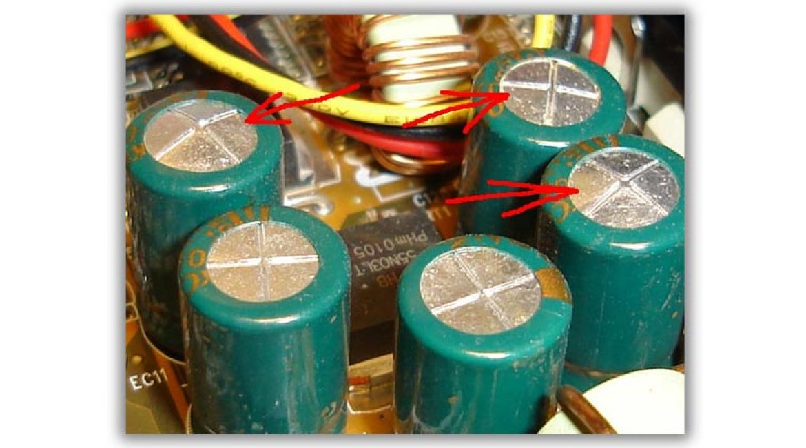
- There was a smell of smoke. The transformer, chokes burned out, and the capacitors swelled.
- The computer power supply is beeping. The fan may need to be cleaned and lubricated. A squeak when turned on is also caused by a crack in the transformer core and swelling capacitors.
In all cases, it is best to contact, where specialists will make a more accurate diagnosis and tell you whether there is any point in further repairing the device.
There is a lot of discussion around the issue of choosing a processor, video card or motherboard, but few people know what without good block power supply all this will not work correctly. This part converts the incoming voltage and distributes it to all elements of the computer. If the “machine” does not turn on, you should first check the power supply.
How to check the functionality of a computer's power supply
A malfunction of the power supply is extremely rare, because all modern models have protection against power surges, overloads and other problems in the network that could damage it. However, if the computer does not turn on, the first priority is not to check the processor, but to test the power supply. As a rule, if there are problems with it, the system unit does not show any signs of life: there is no fan rotation, no noise from the hard drive or motherboard.
To test the power supply, you need to turn off the computer and switch the toggle switch on the back panel of the power supply to the “off” position. For ease of work, the part must be removed from system unit. As a rule, the power adapter is in atx format, which is standard for most case models, and a set of cables for the motherboard, video card, coolers, and hard drive. They should be checked for serviceability first.
Power pin connectors
Checking the computer for functionality begins with the presence of power supply to all elements of the system. To test the power pin connectors, the power supply will definitely need to be turned on, but for this it is not necessary to connect the part directly to the motherboard or anything else. To do this, a paperclip will be enough to close the circuit or a cooler, the main thing is that the power supply does not work “idle”.
If you connected a cooler, then you don’t have to be afraid to turn on the power supply. It is written in the instructions or on the packaging, and often on the device itself, what voltage should be supplied to the lines. Using a multimeter, you can check each one for compliance with the stated indicators. If somewhere the power does not match or the indicator is completely absent, this is where the power supply unit breaks down. This method will be described in more detail in the method for checking the motherboard power cable
Computer power cable

In some cases, the cause of the breakdown is not one of the power supply cables, but the power cord that supplies voltage to the device. It can break if left in the wrong position for a long time, burn where the wire is exposed, etc. This element of the system is the easiest to replace, so when checking the computer's power supply, they simply try to turn it on. To do this you need:
- Connect the cooler as described above so that there is a load.
- If there is no cooler, then you need to close two contacts on the 24Pin (atx) cable.
- Find the green wire and the black wire that will need to be shorted.
- Take a regular paper clip and bend it to form a U shape.
- Insert one end of the paperclip into the green wire, the other into the black wire. This will tell the PSU that it is connected to the motherboard and allow it to turn on.
- After this, you can turn on the device.
- If the cooler of the device starts to spin, it means that power is supplied to it, and the problem is not in the power cord.
- If it does not spin, then the cable or some part inside the computer power supply itself is faulty.
Motherboard power
To check, you will need a 24Pin (ATX) format cord that connects to the motherboard. It is not difficult to find, it is the largest and has 24 pin contacts (the old 20). It already has a paperclip installed if you didn't connect the cooler. All the wires of this cable are painted in different colors, not for the sake of beauty, they indicate specific indicators. The colors mean the following:
- black – earth;
- orange – +3.3V;
- red – +5V;
- yellow – +12;
- green – PS ON (paired with ground, it starts the power supply, which is why the paper clip closes them);
- gray – +5V;
- purple – +5V;
- white – -5V;
- blue – -12V;

Depending on the manufacturer or brand of computer power supply, these values may differ slightly, but most devices meet the characteristics described above. To check the wires you will need a multimeter. One probe (negative, black) must be connected to the black wire, and the second (red) to the contact being tested. You should compare the stated voltage (by color) with the actual voltage. If significant discrepancies are observed somewhere, then the reason incorrect operation This wire can serve as a power supply.
Checking the capacitor with a multimeter
The main task of this power supply element is to preserve, support electric charge and smoothing the voltage in the electrical circuit. For example, everyone has observed the “blinking” of the light, which is essentially a short-term drop in voltage in the network. Power supplies with faulty or bad capacitors cannot withstand such moments and the computer reboots. The good ones at this moment release the accumulated energy and provide sufficient voltage to continue the operation of the system. You can check the capacitor as follows:
- To check the capacitor, you need to set the multimeter to the “ringing” mode.
- If there is none, then measure the resistance with the value set to 2 Kilo-Ohms.
- Place the black probe on the negative leg of the capacitor, and the red one on the positive leg. If you mix it up, nothing bad will happen, but you won’t be able to check either.
- If everything is done correctly, the capacitor will begin to charge. The indicator should be higher than 2M, which indicates the sufficient capacity of the part and its serviceability. If the value is lower than or equal to 2M, the capacitor must be replaced.

How to test a resistor with a multimeter
The above describes in detail how to check the computer power supply cables, but the breakdown does not always lie in them. Sometimes the cause of failure is smaller parts, such as resistors. A burnt part can be detected with the naked eye, but sometimes the problem lies in incorrect resistance. To check you need:
- Turn the multimeter into resistance measurement mode.
- Look at the nominal value either on the resistor itself or on the board next to it. If this data is not available anywhere (Chinese manufacturers apply colored circles), then you can set the value to 2000 Ohms and if it is exceeded, the number 1 will simply appear.
- Set the black probe to the “minus” and the red probe to the “plus” of the resistor.
- If the nominal and actual resistance do not match, the part must be replaced.
- Deviations of 5% are acceptable.
Computer power supply test program
It’s clear how to check a computer’s power supply with a multimeter, but there is an option without having to remove it from the system unit. You can download a program with which you can check the power supply. It is usually used during spontaneous shutdowns, reboots, “ blue screens of death". Before manual diagnosis, it is important to understand what exactly causes such failures. In some cases, the processor or driver is the cause. You can use the OSCT program to check.
This software creates the maximum load on one or another element of the system. It is not recommended to use the program on cheap, weak systems. Inside it there are several tabs that relate to the processor and memory, video card and power supply. The load on a specific element will help determine the problem with it. You need to do the following:
- go to the “power supply” tab;
- set the resolution appropriate for your monitor;
- test type – “manual”;
- duration of the test – 1 hour;
- shader complexity is the optimal parameter offered by the program;
- check the boxes next to “full screen”, “hyper trading”, “64 bit Linckpad”;
- press the “ON” button.

If failures occur during the test, the program compiles a report on the errors that occurred and indicates their nature, which allows you to work with specific problematic elements of the computer. This becomes a good reason to remove the power supply and perform a detailed manual check using a multimeter. Remember that if you disassemble the part yourself, the manufacturer’s warranty obligations are removed.
Video: checking the PC power supply
If your computer often freezes or constantly requires a restart, or does not turn on at all, then possible reason Such problems indicate a malfunction of the power supply.
There are a number of signs characteristic of a malfunctioning battery. The power supply does not work in desired mode under the following conditions:
- Pressing the power button does not start the system unit. There is no light or sound response to switching on. Coolers do not rotate. In such a situation, there may be a malfunction of the power supply or there may be breaks in the wires, weak supply alternating current from the network;
- The computer does not turn on the first time. The problem is either in the power supply, or in a loose connection of the connectors, or in a malfunction of the power button;
- Computer without apparent reason turns off when the operating system boots. The reason for this may be intermittent transmission of voltage from the power supply to other computer components. This malfunction may also indicate that the power supply is overheating and, as a result, it is forced to shut down.
- Presence of a blue screen.
- Presence of a burning smell.
Inspection of the block
Checking the correct operation of the computer power supply involves carrying out certain manipulations under voltage. Be extremely careful to avoid accidents. Before starting the test, inspect the integrity of each cable. Do not touch parts with wet, unprotected hands.
1 Visual check of the power supply.
This is the first and easiest way to check.
- Unscrew 4 (or 6) screws, disconnect the unit from the computer case;
- Unscrew the screws that are in the unit body and disassemble it;
- Carefully inspect the power supply chip. Pay close attention to the capacitors.
If any of them are swollen, then the power supply protection is faulty. Urgent replacement of parts is required.
If no problems are found in the capacitors, we recommend removing dust from the power supply, lubricating the fan and reassembling the device, and then try connecting the computer.
Power check
Read also: TOP 15 Programs for checking your hard drive for errors and bad sectors | Windows (7/8/10)
This test is carried out by turning on the power supply without connecting it to the motherboard.
- Turn off your computer. Then turn off the switch on the back of the computer's power supply.
- Remove the computer cover. Disconnect the power supply from other parts of the computer. Disconnect each cable. Be sure to remember or take a photo of the order in which all the elements are connected so that you can reconnect all the cables later.
- Take the motherboard power cable that comes from the power supply. Find the green wire.
- It must be connected to any of the black wires. Do this using a paperclip or a small piece of wire.
- Connect any device to the power supply. For example, an old unnecessary hard drive. This is necessary to give the power supply a certain load, the absence of which can lead to damage to the unit.
- Connect the power supply to the network and press the power button on the unit body.
If the fan starts to rotate, it means the power supply is working.
Even if this test method showed that the power supply is working, this does not mean that it is completely working.
Checking with a multimeter
Read also: TOP 15 Best programs for data recovery from a flash drive | 2019
Now you need to check whether the power supply transmits full DC voltage. For this:
- Unplug the power supply and use a paperclip or piece of wire to short-circuit the motherboard cable. This will bring the unit into working condition.
- Apply any external load to the power supply. Connect a floppy drive, hard drive or cooler to it;
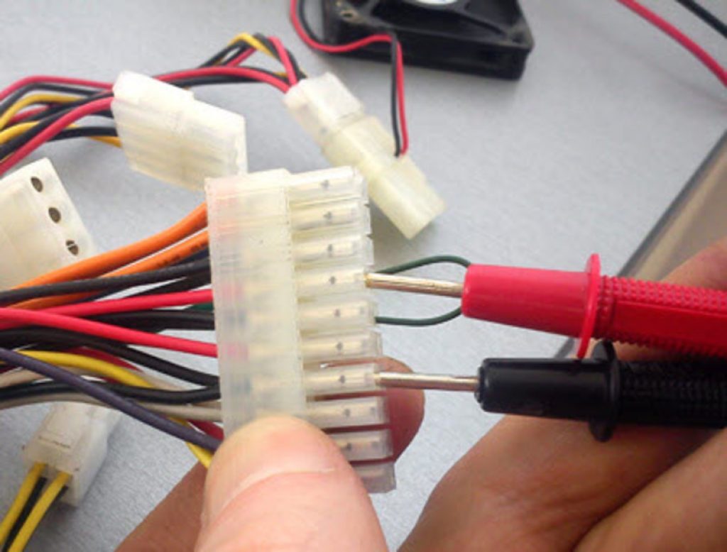
- Take a multimeter - this is a universal tester that measures current strength. Set the tester to DC voltage test mode.
- Check the voltage between the orange and black wires, between the red and black wires, and between the yellow and black wires.
- We plug the black probe of the multimeter into the connector opposite the black wire, and connect the red probe of the tester in turn to the connector contacts to which the wires of the colors we need fit.
A functioning power supply will produce the following voltage values:
- 3 Volts for orange wire;
- 5 Volts for red wire;
- 12 Volts for yellow wire.
If the test you carried out shows that the power supply is faulty, you can disassemble it and repair it. After completing the work, collect all the contacts and install them correctly.
If the test showed that your power supply is working, but difficulties with the computer continue, then most likely the reason is something else.
Software check
Read also: Checking RAM: Basic methods for all operating systems | 2019
You can check the operation of the power supply using the specialized SpeedFan program.
This utility checks the temperature and voltage of the power supply.
When indicating the temperature of the power supply, this program operates with an internal thermal diode.
This allows you to more accurately determine the temperature.
Download
- Universal test program. If the power supply does not overheat, then there are no problems. It is noteworthy that during heating the program loads not only the processor, but also the video card. You can set your own monitoring of voltage and temperature of the power supply - S&M. This utility heavily loads the processor, causing maximum heating of the devices.
Testing with this utility may cause the device to overheat and break if the components are of poor quality.


How to check your computer's power supply. The computer does not turn on.
So, the power cord from the outlet to the computer power supply has been checked. Thus, the required voltage is supplied to the power supply. But when I press the power button, nothing happens and the computer does not turn on. Most likely, we are talking about a faulty power supply. You can independently check the power supply, its serviceability, and at least try to determine why the computer’s power supply is not working.
Well, you will have to free the computer from the side cover on the side of the ventilation hole. It is not necessary to remove the second one. If the fans do not spin when you press the power button, there are only a few options available. The main reasons: the power supply or the power button is faulty. Yes, anything can happen, and it could simply be a faulty button or a broken wire from the button to the connector on the . Let's highlight the direction in which we will move.
What do we need?
- a short in the form of a metal wire, a small piece of wire with a small cross-section; I use a radio element such as a 1 kOhm resistor, but for a one-time experiment a scraper will be enough; however, I advise you not to leave the power supply with a scraper for a long time: the smaller the cross-section, the more our improvised short circuit will heat up
- (if you are going to check not only the performance of the power supply, but also the voltage along the main load channels)
I propose to break the entire verification procedure into the following stages:
Does the button work on its own?
To separate a power supply fault from a button fault, we don’t need to remove the power supply itself just yet. To begin, unplug the computer's power cord from the electrical outlet or turn it off using the button on the back of the power supply.
At open lid trace the path of the power-on wires and “LED” wires from the front panel of the computer to the motherboard. They are not difficult to find, they have a mixed (red, blue, black and green wires) color designation and, ending with jackers, are connected to the male connectors of the motherboard. These connectors are usually located in the bottom quadrant of the board.

Our task is to highlight the connector that is responsible for turning on the computer with a button. The voltage on the motherboard is low and there is no need to be afraid of electrical discharge. The only advice is to try not to damage the motherboard while you are trying to test the power supply using the manipulations described below.
The connector you are looking for is easy to determine. It is indicated by letters with the letters PW or POWER(from English - food). As in the photo below, it almost always has a similar color scheme of wires - green (red or blue) plus white (rarely others). But given the fact that we do not know who assembled our computer, the most the best way determine the identity of any wires, this is the drawing next to these connectors. As you can see in the photo, the right side of the picture is indicated by these letters. So this is the power button. It is connected by two wires and will also help us check the power supply.

The connection diagram is drawn directly on the board, but the connectors themselves are not included in the photo, they are slightly to the right of the shooting area
The indicated symbols are required for the power button. Pull towards you and remove the jack from the connector. Remember it. In the next step, we will connect the protruding pins to each other. The next step is to insert the power cord into a power outlet or turn on the button on the power supply.
Now let's try to check the power supply for startup
Using the flat blade of a small screwdriver, the blade of scissors or a paper clip, briefly bridge the motherboard contacts released from the power button jack as shown in the photo. Try several times.

- If the power supply is working and the computer itself is working, the computer will turn on and continue to work. You can turn off the computer by simply turning off the button on the power supply, unplugging the cord from the socket, or re-closing the same contacts with a screwdriver, but holding it until it turns off.
- If the coolers of the power supply, cooling the processor and blowing the system unit (if any) turned on, but this did not happen from the button assembly, the power supply is in order and the fault lies in the power button.
- If the computer does not respond to manipulations, proceed to the next step.
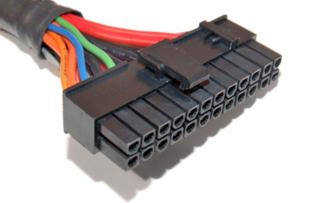
Disconnect the main ATX connector, coming from the power supply to the motherboard. This is the largest connector, it cannot be confused with anything. This is a 24-pin (or 20+4) connector:

The camera flash ruined the view a little...
Press the plastic lock on the side with your thumb (or forefinger) to release the connector for removal, and pull the connector towards you using a swaying longitudinal motion. If necessary, rest your free fingers on the motherboard. Don't break it (although I've never broken it).
 Now let's try to check the power supply and start it directly
In the assembled circuit, the signal to turn on comes from the button through the motherboard to the green contact of the connector that you hold in your hands. We will bypass the board and close this contact to any of the black wires. To check the power supply, contact closure black and green flowers will be held for a short time. This means you can use any available means: a paper clip, tweezers, etc. Do not be afraid of electric shock, the voltage in this part of the system is absolutely safe. The contacts that will be closed are located nearby: they have a conventional numbering 15 And 16 (remember this: the numbering will be useful to us when searching for other contacts). The black wire is “ground” (empty), the green wire carries voltage when plugged into the socket. You can close it directly when it is plugged into the socket in the power supply; you will not get hurt, the voltage is negligible and is not dangerous for a person:
 If the power supply continues to be silent, the coolers do not want to spin, the fault lies in the power supply. In the language of electrical engineering, this means that the voltage in this section of the power supply circuit is less than the required 5 V. More about this in another article. You can call a specialist or continue the search yourself.
It's time to check the power supply using the device
If the power supply comes to life, we proceed to measurements with the device. Turn off the power supply for a while. Set the multimeter to constant voltage measurement mode. On the device carriage this is a sector with symbols V – :

and immediately set the measurement limit to 20 volts:

I’ll remove the main consumers (disks, drives, power supply to the video card) of the computer from the power and signal cables:

HDD disabled
And behind it is a DVD drive:

We plug the computer into a power outlet or using the button on the power supply unit at the back. With the power supply turned on (the cooler in it is spinning), I check the voltage at the terminals of the 24-pin 12V power supply. is given in the article of the same name. We shorted the wires with numbers 15 and 16. And here’s how the numbering itself goes:


Two (usually orange on the edges) in the opposite row from the green - 1 And 2 . And so on from left to right. The next row is also numbered from left to right. Look at the photo.
We insert the black probe of the device into the contact of a black connector for a long time (this will be the contact 3 ). It is located just opposite the black contact 15 busy with scraper. In the language of specialists, this is called “planting the probe on the ground”; we will not remove it from the connector while taking measurements (you can fix it there, just don’t overdo it):

Using the red probe of the device, we will one by one check the amount of output voltage on all channels of the unit (I’ll say right away - the experimental power supply is healthy) and start with 1 th:

The second contact of the connector shows the same parameters:

The next contact number to be tested is 4 – this is 5 volt. Let's check ( Don't get burned on the scraper!):

And so on. And thus, from contact to contact, you must gradually compare the passport readings of the power supply pinout (see link above) with the readings of the device. That is, the multimeter readings will approximately coincide (with a small error) with the readings in the article’s table. Please note that the contact 3 with contacts 5 , 7 , 17 , 18 , 19 , 24 The device should not respond.
ATTENTION . The next step is to try to test the power supply under load. All measurements just taken will be carried out in the same way, but with the connector connected to the board. When I carried out such measurements for the first time, I partially numbered (to avoid confusion) the wires on the connector with labels made of electrical tape. I advise you too. Everything is not necessary - just note starting point and counting order. The color of the wire will remind you of the voltage indicators.
Check the power supply under load
If the voltage values of the pinout table and the multimeter readings when the power supply is idling coincide (measurement errors within a fraction of a percent are acceptable and preferably larger), let’s try to check the power supply under load. Let's assemble the circuit, connecting all the cables, and turn on the computer. DO NOT CLOSE THE COVER YET! We need BIOS and type tab Power with point Hardware Monitor (BIOS versions there are many, their interface is different - so don’t blame me). I have so:


The tab displays voltage values as the BIOS sees them. As you can see, the read information coincides with the measured ones. The power supply is working fine. But now it’s worth checking the indicated readings on the screen with the readings of the multimeter when working under load. We insert the power supply connector into the female connector of the motherboard, connect all devices, turn on the computer and check with the device in the same order, also sequentially changing the probes in the set measurement range, but in this manner:

I think I have helped you draw some conclusions about the performance of the power supply. Of course, all these conclusions are superficial, and the purity of the power supply can only be said with an oscilloscope.
Nowadays, many devices are powered by external power supplies - adapters. When the device has stopped showing signs of life, you first need to determine which part is defective, in the device itself, or the power supply is faulty.
First of all, an external examination. You should be interested in traces of a fall, a broken cord...
After an external inspection of the device being repaired, the first thing to do is check the power supply and what it outputs. It doesn't matter whether it's a built-in power supply or an adapter. It is not enough to simply measure the supply voltage at the power supply output. Needs a small load A. Without load it may show 5 volts, under light load it will be 2 volts.
An incandescent lamp at a suitable voltage does a good job of acting as a load.. The voltage is usually written on the adapters. For example, let's take the power adapter from the router. 5.2 volts 1 amp. We connect a 6.3 volt 0.3 ampere light bulb and measure the voltage. A light bulb is enough for a quick check. Lights up - the power supply is working. It is rare for the voltage to be very different from the norm.
A lamp with a higher current may prevent the power supply from starting, so a low-current load is sufficient. I have a set of different lamps hanging on the wall for testing.
1 and 2 for testing computer power supplies, with more power and less power, respectively.
3
. Small lamps 3.5 volts, 6.3 volts for checking power adapters.
4
. A 12-volt automotive lamp for testing relatively powerful 12-volt power supplies.
5
. 220 volt lamp for testing television power supplies.
6
. There are two garlands of lamps missing from the photo. Two of 6.3 volts, for testing 12 volt power supplies, and 3 of 6.3 for testing laptop power adapters with a voltage of 19 volts.
If you have a device, it is better to check the voltage under load.

If the light does not light, it is better to first check the device with a known good power supply, if one is available. Because power adapters are usually made non-separable, and to repair it you will have to pick it apart. You can't call it dismantling.
An additional sign of a malfunctioning power supply can be a whistle from the power supply unit or the powered device itself, which usually indicates dry electrolytic capacitors. Tightly closed enclosures contribute to this.
The power supplies inside the devices are checked using the same method. In old TVs, a 220 volt lamp is soldered instead of a line scan, and by the glow you can judge its performance. Partly, the load lamp is connected due to the fact that some power supplies (built-in) can produce significantly higher voltage without load than required.
Publications on the topic
-
 Bypass: "This product is not available in your region"
My acquaintance with the famous online store happened at the end of 2012. I live in Yakutia, a remote region, but not remote. The only one...
-
 The best Android smartphone under 10000
Hello everyone, Zhora from the MYLMA team is here again for another review. Watching people on the streets, I came to the conclusion that approximately the majority...