
Hidden wiring break indicator diagram. Hidden wiring detector - make the simplest analogue and select the device in the store

In this article we will talk about simple circuits of hidden wiring indicators on transistors and microcircuits.
A device such as a hidden wiring indicator becomes necessary when repairs are being carried out in a room, and where and how the electrical wiring is installed is unknown. The probability of breaking the wiring at this time becomes quite high and the law of meanness is triggered: the electric drill drill hits the wiring exactly, which in the best case leads to its breakage, and in the worst case – damage to the electric drill or electrical injury.
To detect hidden electrical wiring, in most cases, a simple device consisting of a field-effect transistor and a pointer ohmmeter is sufficient. The principle of operation of the device is based on the property of a field-effect transistor - to change its resistance under the influence of interference at the gate terminal. When searching for hidden wiring, the transistor body is moved along the wall and the location of the wiring is determined by the maximum deviation of the device arrow.
 A more advanced option is to use a field-effect transistor, a headphone and one or three batteries (see figure). Transistor VT1 - type KP103, KP303 with any letter index (in the latter, the housing terminal is connected to the gate terminal). The BF1 telephone is high-impedance, with a resistance of 1600...2200 Ohms. The polarity of connecting the GB1 battery does not matter.
When searching for hidden wiring, the transistor body is moved along the wall and the maximum sound volume with a frequency of 50 Hz (if it is electrical wiring) or radio broadcasts (radio broadcast network) is used to determine the location of the wires.
Indicators of hidden wiring on transistors
A relatively simple device made with three transistors will help determine the location of hidden electrical wiring in the walls of a room (see figure). A multivibrator is assembled on two bipolar transistors (VT1, VT3), and an electronic switch is assembled on a field-effect transistor (VT2).
 The operating principle of the hidden wiring indicator is based on the fact that an electric field is formed around the electrical wire, and the finder picks it up. If the SB1 switch button is pressed, but there is no electric field in the area of the WA1 antenna probe, or the hidden wiring indicator is located far from the network wires, the VT2 transistor is open, the multivibrator does not work, and the HL1 LED is off.
It is enough to bring the antenna probe of the hidden wiring indicator, connected to the gate circuit of the field-effect transistor, closer to the conductor with current or simply to the network wire, transistor VT2 will close, the shunting of the base circuit of transistor VT3 will stop and the multivibrator will start working. The LED will start flashing. By moving the antenna probe near the wall, it is easy to trace the route of network wires in it.
The field-effect transistor can be any other from the series indicated in the diagram, and bipolar transistors can be any from the KT312, KT315 series. All resistors - MLT-0.125, oxide capacitors - K50-16 or other small ones, LED - any of the AL307 series, power source - Corundum battery or accumulator battery voltage 6...9 V, push-button switch SB1 - KM-1 or similar.
The body of the Hidden Wiring Indicator can be a plastic pencil case for storing school counting sticks. The board is mounted in its upper compartment, and the battery is placed in the lower compartment. A switch and LED are attached to the side wall of the upper compartment, and an antenna probe is attached to the top wall. It is a conical plastic cap, inside of which there is a metal rod with a thread. The rod is attached to the body with nuts; from inside the body, a metal petal is placed on the rod, which is connected with a flexible mounting conductor to resistor R1 on the board. The antenna probe can be of a different design, for example, in the form of a loop from a piece of thick (5 mm) high-voltage wire used in a TV. The length of the segment is 80... 100 mm, its ends are passed through the holes in the upper compartment of the case and soldered to the corresponding point on the board.
The desired oscillation frequency of the multivibrator, and therefore the LED flash frequency, can be set by selecting resistors R3, R5 or capacitors C1, C2. To do this, you need to temporarily disconnect the source output of the field-effect transistor from resistors R3 and R4 and close the switch contacts.
The wiring indicator can also be assembled according to a slightly different scheme using bipolar transistors of different structures - a generator is made on them. The field-effect transistor (VT2) still controls the operation of the generator when the antenna probe WA1 enters the electric field of the network wire.
Parts used: C1-5...10 µF, VT1-KT209 or KT361 with any index, VT2-KP103 any index, VT3-KT315, KT503, KT3102 with any index, R1 50K-1.2M, R2 150-560 Ohm. Antenna made of wire 80…100 mm.
Indicators of hidden wiring on microcircuits
 The circuit of the simplest indicator on a CMOS chip is shown in the figure.
Element DD1.1 is an electromagnetic radiation detector, and element DD1.2 is a signal repeater. When wiring is detected, the piezo emitter HA1 will operate at a network frequency of 50 Hz. A piece of copper wire 5...10 cm long serves as an antenna. The sensitivity of the detector depends on its length. If the length is more than 15 cm, this can lead to self-excitation of the circuit, so its length should not be abused.
Four A316 type galvanic cells connected in series can be used as a power source.
 The following figure shows a diagram of a more complex version of the indicator on a CMOS chip, which, in addition to sound, also has a light indication of the presence of electromagnetic radiation.
It is built on a DD1 chip of the K561LA7 type, and all its elements are used. The circuit consists of an electromagnetic radiation detector on element DD1.1, a low-frequency generator (operating frequency about 1 kHz) on elements DD1.2, DD1.3 and an inverter DD1.4, which controls the HL1 LED. The circuit does not need to be configured.
 The following indicator circuit consists of two components - an AC voltage amplifier, which is based on the micropower operational amplifier DA1, and an oscillator audio frequency, assembled on an inverting Schmitt trigger DD1.1 of the K561TL1 microcircuit, a frequency-setting circuit R7C2 and a piezo emitter BF1.
When the WA1 antenna is located close to the current-carrying wire of the power supply network, the pickup of the EMF at an industrial frequency of 50 Hz is amplified by the DA1 microcircuit, as a result of which the HL1 LED lights up. This same op-amp output voltage, pulsating at 50 Hz, drives the audio frequency oscillator.
The current consumed by the device microcircuits when powered from a 9 V source does not exceed 2 mA, and when the HL1 LED is turned on - 6...7 mA. The power source can be a 7 D-0.125 battery, “Korund” or a similar one made abroad.
Sometimes, especially when hidden wiring is located high, it is difficult to observe the glow of the HL1 indicator and an audible alarm is sufficient. In this case, the LED can be turned off, which will increase the efficiency of the device. All fixed resistors are MLT-0.125, adjusted resistor R2 is SPZ-38B type, capacitor C1 is K50-6. The WA1 antenna is a foil pad on a board measuring approximately 55x12 mm.
The circuit board of the hidden wiring indicator is placed in a housing made of dielectric material so that the antenna is in the head part and is as far as possible from the operator’s hand. On the front side of the case there is a power switch SA1, an LED HL1 and a sound emitter BF1. The initial sensitivity of the device is set with a trimming resistor R2. An error-free mounted device does not require adjustment.
There are also more complex hidden wiring indicators, but they are needed more by professionals rather than amateurs.
Industrially produced detectors are often combined - they contain several types of detectors:
·
Electrostatic. Pros – simple, long detection range.
Cons – they don’t work on damp walls (they show that the wiring is everywhere). Requires voltage in the wiring.
·
Electromagnetic. Pros – simple, good detection accuracy.
Cons - they require not only the voltage in the network, but also that the wire be loaded with a powerful load, usually on the order of kilowatts.
·
Metal detectors. They're just looking for metal in the walls. Pro – you can search without voltage.
Cons: complicated, foreign metals interfere. If a nail is hammered somewhere nearby, then nothing good will come of it.
Hidden wiring indicators
Resistor R1 is needed to protect the K561LA7 microcircuit from increased voltage of static electricity (as practice has shown, it does not need to be installed). The antenna is a piece of copper wire of any thickness. The main thing is that it does not bend under its own weight, i.e. was quite tough. The length of the antenna determines the sensitivity of the device. The most optimal value is 5...15 cm. When the antenna approaches the electrical wiring, the detector emits a characteristic crackling sound.
The device is convenient for determining the location of a burnt-out lamp in a Christmas tree garland - the cracking stops near it. The ZP-3 type piezo emitter is connected in a bridge circuit, which provides increased volume.
 In Fig.2 shows a detector with sound and light indication.
The resistance of resistor R1 must be at least 50 MOhm. There is no current-limiting resistor in the VD1 LED circuit; the DD1 microcircuit (K561LA7) copes well with this function itself.
HIDDEN WIRING INDICATOR DIAGRAM.

Details:
- C1...C5 - 10 µF;
- VT1 - KT209x or KT361x;
- VT2 - KP103x;
- VT3 - KT315x, KT503x or KT3102x;
- R1 - 50K…1.2 M;
- R2 - 150…560 Ohm;
- Antenna 80…100mm.
Device for detecting hidden wiring
 The circuit is powered by 3-5 V. The circuit runs on two watch batteries continuously for about 6 hours. The antenna is a coil wound with 0.3 or 0.5 mm wire on a 3 mm frame. The reel can be used both on a frame, in the form of a rod, and in a frameless form.
Depending on the thickness of the wire, a certain number of turns are wound, with wire 0.3 mm - 25 W, 0.5 mm - 50 W.
The setup comes down to selecting resistor R1*; it adjusts the maximum volume of the main phone, depending on its resistance.
In the circuit, instead of the KP103 field-effect transistor, you can use KP303D.
A device for detecting breaks in electrical wiring.
 The following device can be easily placed in a marker, the antenna can be pulled out through the hole for the rod, the length of the antenna is 5-10 cm, if you need a sensitivity of no more than 5 - 10 cm, then the length of the gate of the field-effect transistor is sufficient for the antenna.
Field-effect transistor VT1 (Fig. 1) acts as a sensor that “captures” even very weak electric field strength. Therefore, when the finder field-effect transistor is near the phase wire of the lighting network, the resistance of its drain-source section will decrease so much that transistors VT2, VT3 will open. LED HL1 will flash. The field-effect transistor can be any of the KP103 series, and the LED can be from the AL307 series. Bipolar transistors can be any low-power silicon or germanium structure indicated in the diagram and with the highest possible current transfer coefficient. Resistors - MLT-0.125. Transistor VT2 (KT203) can be replaced with KT361. When mounting a field-effect transistor, it is placed horizontally on the board, and the gate lead is bent so that it is above the transistor body. If during operation of the finder it is revealed that it is excessively sensitive, the shutter lead is shortened.
A simple contactless probe.
Only two elements - the DD1 microcircuit and the HL1 LED - make up the circuit of this probe; the K176LP1 microcircuit contains three p and three n-channel CMOS transistors. By connecting the pins of the microcircuit in such a way as to form a chain of three inverters, you can get a device that fairly well amplifies the currents induced by the alternating voltage field in the phase wire of the power network.
An LED is turned on between the output of the last inverter - pin 12 of DD1 and the plus of the probe power supply. It lights up when a phase network wire is placed close to pin 6 of the microcircuit.
The LED will go off if, by running the probe along the faulty wire connected to the electrical network, you reach the break point.

Combining inverters into a chain must be done by connecting the following DD1 pins:
1. Option for connecting the microcircuit pins: 3, 8 and 13; 2 and 10; 4, 7 and 9; 1 and 5; 11 and 14.
2. Option for connecting the microcircuit pins: 3,8,10 and 13; 1, 5 and 12; 2.11 and 14; 4,7 and 9.
The sensitivity of the probe is such that it does not necessarily need to touch the insulation of the wires being tested. The current consumption does not exceed 3 mA - at a battery voltage of 4 -5V.
The length of the conductor - the “probe” of the probe leading to pin 6 of the microcircuit should be no more than 15 - 20 mm. The switch in the probe is optional, since in non-operating mode the circuit consumes a negligibly small current, due only to the static current in the CMOS transistors of the inverter chips.
Hidden wiring finder circuit - alternating electric field indicator

A simple indicator of an alternating electric field of hidden wiring can be assembled using a voltage divider - resistor R1 and a field-effect transistor channel - as a voltage divider controlled by an external electric field. A generator based on the K122TL1 microcircuit was used as a controlled pulse generator. The generator load for indication is high-impedance headphone type TON-1 (TON-2)
In the presence of an external alternating electric field, the signal induced by the antenna is supplied to the control electrode of the field-effect transistor (gate), which causes modulation of the resistance of the field-effect transistor channel. As a result, the voltage drop across the divider changes, which, in turn, causes generation to occur with a changing frequency.
Indicator of hidden wiring on microcircuits
The circuit consists of an AC voltage amplifier, the basis of which is the operational amplifier DA1, and an audio frequency oscillation generator assembled on a Schmitt trigger DD1.1 (K561TL1), a frequency-setting circuit R7C2 and a piezo emitter BF1.
When the WA1 antenna is located close to the phase wire of the power supply network, the pickup of the EMF at an industrial frequency of 50 Hz is amplified by the DA1 microcircuit, as a result of which the HL1 LED lights up. This same op-amp output voltage, pulsating at 50 Hz, drives the audio frequency oscillator.
The current consumed by the device microcircuits when powered from a 9V source does not exceed 2 mA, and when the HL1 LED is turned on - 6...7 mA.
The WA1 antenna is a foil pad on a board measuring approximately 55x12 mm.

The circuit board is placed in a housing made of dielectric material so that the antenna is in the head part and is as far as possible from the operator’s hand. On the front side of the case there is a power switch SA1, an LED HL1 and a sound emitter BF1.
The initial sensitivity of the device is set by trimming resistor R2. An error-free installed device does not require adjustment.

The signal from an antenna 200 mm long is fed to the operational amplifier DA1 K140UD7. From output 6 DA1, the amplified signal is supplied to the rectangular pulse shaper DD1 K561LA7 and then to the output stage VT1, lighting the HL1 LED. It is advisable not only to see, but also to hear this signal. It is not advisable to connect the sound emitter in parallel with R5, HL1. For sound, a multivibrator is used on the KR1006VI1 timer. Capacitors C1, C2 select a pleasant sound and its duration, as well as the glow of the HL2 LED. In this version, the sound frequency is 1.7 kHz.
Depending on the insulation and the depth of the wires in the wall, the sensitivity can be changed by touching the common wire with your hand through a small capacitance capacitor SZ 27...33 pF, without bringing the device to self-excitation. With a larger capacity, the device will be excited.
The device is powered by 3 AA batteries connected in series with a total voltage of 4.5 V. When using the device, it is necessary to turn off powerful sources of the electric field: transformers, televisions, fluorescent lamps. A piezo emitter from telephone sets is used as a sound emitter.
LEDs HL1 - green, HL2 - red.
Device for detecting damage to hidden electrical wiring

The device is powered by an autonomous 9v source and is housed in an aluminum case measuring 80x38x27 mm.
Principle of operation:
One of the wires of the hidden electrical wiring is supplied with 12V alternating voltage from a step-down transformer. The remaining wires are grounded. The device turns on and moves parallel to the wall surface at a distance of 5...40 mm. In places where the wire is broken or terminated, the indicator goes out. The device can also be used to detect core damage in flexible cables and hose cables.
Hidden wiring detector
The device will save you from the possible risk of hitting a wire with a drill when drilling a hole in the wall, it will allow you to trace the path of the wire and in many other cases when it is necessary to detect hidden wires.
A piece of wire or a metal rod with a diameter of about 5 mm and a length of 70...90 mm is used as a sensor.
The principle of operation of the circuit.
A low-frequency multivibrator is assembled using bipolar transistors VT1 and VT3. Its operating frequency is determined mainly by the capacitor ratings, which are aluminum, niobium or tantalum electrolytic capacitors.
In the initial state, when the antenna probe of the device is removed a considerable distance from the hidden wiring, field-effect transistor VT2 is in cutoff mode. In this case, across resistor R4, which is connected to the source circuit of transistor VT2 (KP103D), a voltage drops approximately equal to 3.5 volts. In this case, the potential of the VT3 base is fixed at a level that keeps VT3 in a saturated state and the LED glows continuously. Transistor VT1 is in cutoff mode at this time. 
When the antenna probe approaches the place where the wire is hidden, where an alternating potential of 220V is maintained, the electrical component of the electromagnetic field of the network wire induces an alternating potential equal to hundreds of millivolts-units of volts at the antenna input. In this case, the corresponding half-cycles of the input signal open VT2, the current through resistor R4 increases, and therefore the voltage drop across it increases. The potential of the base of VT3 relative to the emitter of VT3 becomes low, putting VT3 in cutoff mode.
As a result, the LED begins to blink, indicating the presence of hidden wiring in this place.
RADIOAMATOR 11"2001
HIDDEN WIRING FINDER
When a 50 Hz signal is detected, the LED will flash at a frequency of approximately 1.56 Hz and the audio signal will be interrupted at the same frequency.
Let's look at the diagram (Fig. 1).
 Antenna W 1 - piece of installation wire about 25 cm long, located along the perimeter of the narrow side part of the device body. On transistors VT 1 and VT 2 a simple amplifier is made - a logic pulse former. It amplifies the signal induced in the antenna and feeds it to the meter D 1 (input “C”). From the number of outputs of a multi-bit counter K561IE16 analogue 4020BEY( D 1) only the output with the weighting coefficient “16” is used. That is, the state of this output changes every 16 input pulses, which means the frequency division is 32. Thus, when receiving a signal with a frequency of 50 Hz, the frequency here will be 1.5625 Hz. The LED will blink at this frequency. H.L. 1, connected to this meter output through an intermediate transistor switch - current amplifier ( VT 3) to make working with the device easier, there is a sound alarm made on a microcircuit D 2. This is a multivibrator circuit that produces pulses with a frequency of about 2000 Hz. On the elements D 2.1 and D 2.2 the multivibrator itself was made, and the elements D 2.3 and D 2.4 form a voltage amplifier that raises the potential difference between the terminals of the piezoelectric sound emitter B.F. 1 is twice the rated voltage of the logic one level.
The multivibrator is controlled - for it to work you need to apply logic one voltage at pin 13 of element D 2.1. Thus, the sound is turned on simultaneously with the indicator LED turning on. The device is powered by a 9-volt Krona battery. Switch S 1- button without fixation. When you are looking for wiring, you need to keep it pressed, release it, and turn it off (this was done to save battery). Sound emitter B.F. 1 - from a faulty multimeter. The printed plate is located above the chip D 2 (glued).
The K561IE16 counter can be replaced with almost any binary CMOS counter that has an output with a weighting coefficient of “16”. This could be K561IE20, K176IE1, or two counters of the K561IE10 chip connected in series. But in any case, the printed circuit board will need to be redesigned.
The printed circuit board is shown in Figure 2.
The board contains all the parts except the antenna and power supply. No setup required.
BINARY HIDDEN WIRING FINDER
The probe circuit consists of a probe-antenna, a transistor amplifier-pulse shaper and a counter with an indicator LED at the output.
 The antenna picks up the electromagnetic field, and the output amplifier stage Pulses appear on VT1 and VT2, the frequency of which is equal to the frequency of the input signal. If this is a wiring signal, then, of course, the pulse frequency will be 50 Hz. If it is a radio signal, then the pulse frequency will be much higher.
The probe works like this:
When the electromagnetic field emitted by the electrical wiring arrives at the antenna, pulses with a frequency of about 1.56 Hz appear at the meter output, and the indicator LED flashes evenly at the same frequency. If, however, a radio signal is received at the antenna, the frequency of which is significantly higher than 50 Hz, the LED blinks much faster and this is visually perceived as its constant glow with a slightly reduced brightness. Or, it does not light up at all, since the K561 series microcircuit may not miss the signal too much high frequency.
To tune out weak but highly interfering radio signals, there is a variable resistor R1, which can be used to adjust the sensitivity of the probe input.
The device is powered by Krona, a small-sized 9V battery.
 The probe is made in the form of a miniature device housed in a suitable housing.
The antenna is a piece of winding wire with a diameter of about 1 mm and a length of about 30 cm, which is wound turn to turn on the front of the housing and secured.
Variable resistor R1 is made from a tuning resistor, with a homemade handle (from a plastic thumbscrew).
Practically no adjustment is required, only if the size of the antenna is selected.
WIRING FINDER
The peculiarity of this wiring finder is that it not only shows the location of electrical wiring, but can also estimate its depth, and also allow you to detect a radio bug or other device transmitting or emitting radio waves. With its help, you can determine which part of the wiring is more loaded and which is less loaded.
Circuit diagram 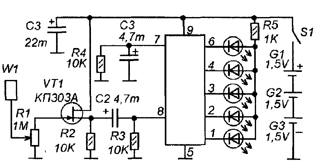 shown in the figure.
Antenna W 1 is a tin plate measuring approximately 60x60 mm. The plate is connected to the input through a variable resistor R1, which can be used to adjust the sensitivity level of the device. Transistor VT 1 has a cascade that increases the input resistance of the device. The alternating interference voltage from its output through capacitor C1 is supplied to an alternating voltage level meter made on the DA1- chip AN 6884(KA2284), switched on according to a standard circuit.
The voltage level of network interference is indicated on a scale of five LEDs HL 1-HL 5 - A L307.
The device is assembled in the housing of a faulty remote control remote control video player "Orion -688". The battery consists of three “AA” cells with a total voltage of 4.5V. Two elements are located in the battery compartment of the remote control, and one more is located directly in the remote control body. Next to this element there is a DA1 chip with LEDs. The antenna plate is located at the front of the body and is curved in shape.
CONSTRUCTION METAL DETECTOR
It will help you detect electrical wiring, pipes walled up in the wall, and even studs under the wallpaper. Its depth of action is not great; it will find studs if the layer of wallpaper or plaster above it is no more than 5 mm, a water pipe at a depth of up to 200 mm, and electrical wiring at a depth of 20-30 mm.
 The metal detector consists of a high-frequency generator on transistor VT 1, operating at a frequency of about 100 kHz, a detector of this RF voltage on transistor VT 2 and an indication circuit on transistors VT 3-VT 4 and an LED HL 1.
The RF generator coils are wound on a ferrite rod (as for the magnetic antenna of an AM receiver). The operating mode of the generator is set at the edge of failure, but so that in the presence of all the metal objects that are part of the metal detector, it works. At the same time, transistor VT 2, under the influence of RF voltage supplied to its base, is open and the voltage at its collector is so low that transistors VT 3 and VT 4 are closed and the LED HL 1 does not light up.
When a metal object approaches the magnetic antenna, the generation amplitude of the RF generator begins to decrease with its further breakdown. The RF voltage at the base of VT 2 decreases or stops flowing and the transistor VT 2 closes. Constant pressure on its collector increases (through resistor R 4) and reaches a level at which transistors VT 3 and VT 4 open and the LED HL 1 lights up.
Thus, movements of the device relative to a metal object will be indicated by blinking of this LED, and moreover, small movements will also affect the brightness of the LED. But, of course, this will only be possible with precise adjustment of the device, which needs to be repeated from time to time (for this there are two adjustable resistor regulators, which are located on the top panel of the plastic case).
 Coils L 1 and L 2 are wound on a ferrite rod with a diameter of 8 mm and a length of about 100 mm. They are located nearby. L 1 contains 120 turns, and L 2 - 45 turns. Wire type PEVTL 0.35.
The metal detector is powered by an imported analogue of the Krona battery.
Setting up.
Having positioned the device away from metal objects (remove the watch from your hand), adjust resistors R 3 and R 5 (using the successive approximation method) so that the device is on the verge of failure of generation (the LED shines at a reduced brightness and unevenly). Then, leaving R 5 alone, continue adjusting R 3 so that the LED goes out. Next, they test the device at a five-kopeck moment, achieving the greatest sensitivity by adjusting R 3 and R 5.
HIDDEN WIRING FINDER WITHOUT POWER SOURCE.
It differs from many similar ones in that it does not require its own power source or any other devices or measuring instruments.
The device diagram is shown in Fig. 1.

The source of energy is the same alternating current network, which we are afraid of damaging with a nail, electric drill or hammer drill. When the device is supplied with an AC supply voltage of 220 V, the large-capacity storage capacitor is quickly charged to the opening voltage of the zener diode VD1. After charging the capacitor C1, the device can be removed from the outlet. The search for the wiring location is carried out in the usual way. When antenna WA1 is located near the electrical wiring location, field-effect transistor VT2 opens at the frequency of the AC mains, LED HL1 begins to glow. The closer the electrical wiring is located, the brighter it shines. Transistor VT1 operates as a micro-power zener diode with a stabilization voltage of 6...10V. Additionally, it serves as a high-resistance discharge resistor for the gate-source transition of transistor VT2. Button SB1 without fixing the position is designed to check whether there is sufficient charge on the plates of capacitor C1. As the voltage on capacitor C1 decreases, the sensitivity of the device does not change, but the brightness of the LED decreases. The E1 sensor is designed so that, if necessary, you can increase the sensitivity of the device, for which you need to touch it with your finger. Resistors R3, R4 limit the pulse current flowing through the diodes of the rectifier bridge when the device is connected to the network. Details: Instead of the KP504A transistor, you can use any of the KP501, KP502, KP504, KP1064KT1, KP1014KT1, ZVN2120, BSS88, BSS124 series.
The pinout of some transistors is shown in the figure.
 The HL1 LED must be super bright, for example, “red” L-1503SRC/F, L-1503SRC/E, L-1513SRC/F. Good results were also obtained with modern super-bright blue and white glow. Any low-power zener diode VD1 for a stabilization voltage of 18...20 V, for example, 1N4747A, KS218Zh, KS520V. With absence
Two such zener diodes can be installed, connected in series D814B1 or 1N4739A. Instead of the VD2 diode bridge, you can use any small-sized one from the KTs422, KTs407, DB101... DB107, RB151... RB157 series. Film capacitor C2 of types K73-17, K73-24, K73-39 for an operating voltage of 630 V and a capacity of 0.1...0.25 μF. Oxide capacitor C1 is the largest part of the device; the author used a relatively small-sized one from Philips. This capacitor should have as little leakage current as possible. Capacitors with a higher operating voltage usually have lower leakage current among capacitors of the same capacity and brand. The sensor can be made from the metal casing of a faulty transistor, for example, KT203, MP16... MP42.
If the device operates unstably, then a high-resistance resistor with a resistance of 100... 200 MOhm should be connected to the gate and source terminals of VT2. If desired, the device can be upgraded. For example, as follows. If you install an LED in series with the zener diode VD1 (anodes together), then this LED will signal that capacitor C1 is fully charged. If you install a piezoceramic sound emitter with a built-in generator, for example, NPA17AX, in series with the HL1 LED, observing the polarity, then together with the glow of the HL1 LED, the sound emitter will generate an intermittent tone - the device will become more informative. When setting up your device, do not forget to disconnect it from the network.
The following circuit contains the electrostatic type of wiring detection.

Scheme:
The antenna is induced by voltage from the wiring. It is detected by a diode at U1A and C5. A voltage-controlled oscillator is assembled on U1D, U1C and Q3 are an amplifier for the piezo tweeter.
We work like this - we lean it against the wall, where there is definitely no wiring, and adjust the sensitivity so that the detector groans slightly. We move and where the tone becomes higher, that’s where our wiring is.
*Functional analogs: K544UD14, KM1401UD4, 1435UD4, LF347, TLO84


The circuit is built into a suitable housing, for example from a TV remote control.
Finding electrical wiring using special devices is not a difficult task. It all depends on the quality, cost of the device, as well as correct settings and the ability to use it. What should you do if you don’t have any instruments at all, and you need to find the wiring right now.
Here we need to remember the old effective methods, which often help, but you still shouldn’t rely on them with 100% probability. Moreover, some Chinese wiring indicators cost mere pennies, but allow you to narrow the search space to a few centimeters. 
Removing wallpaper
 If you are carrying out a major renovation at home, and the current state of the walls and wallpaper does not bother you too much, you can simply rip off all the excess from the wall, right down to the base (brick or concrete). Old grooves can then be visible visually, or palpable by touch, thanks to bulges or, conversely, characteristic indentations.
If the wall is not plastered at all, and there is bare concrete under the wallpaper, then the cable grooves will be 100% visible even to the naked eye.
Searching for wires in the wall with a radio
 Another way is to use an ordinary radio. You tune it to a frequency of one hundred kilohertz and bring it as close as possible to the wall in the place where the wire is supposed to pass. The wire must be live.
To create significant noise and interference, plug in a razor, or a high-speed grinder, drill, or vacuum cleaner.
If you guessed the location of the cable, the receiver will start to crackle. The closer to the strobe, the stronger it is.  Instead of a radio receiver, you can also use a reel-to-reel microphone; connect it to a tape recorder with speakers to reproduce sound interference.
Finding wiring with a multimeter
This method is suitable for radio amateurs. There is no need for special testers to search here, but you do need to have a simple Chinese multimeter and a field-effect transistor. The polevik can be one of the following brands: KP103A, KP303 or 2SK241. 
Turn on the multimeter to measure resistance (200 kOhm), and connect its probes to the left and middle terminal of the transistor (drain + source).  The right pin is used as an antenna. The operating principle of the device is that when a field-effect transistor enters an electromagnetic field, its internal resistance changes. And the multimeter records just this.
Where the change in resistance is maximum is where the wiring is located.
 If you attach an additional antenna (a piece of copper wire) to the third pin, the sensitivity of the device will increase sharply.
Video on searching for wiring with a multimeter:
Correct wiring diagram
 This method is applicable when the wiring in your home was done by professionals. According to the rules, electrical cables and wires can only be laid in vertical and horizontal directions. Laying wiring diagonally is prohibited. In this case, the minimum distances from the groove to the ceiling, doors, etc. must be maintained. You can find out about these distances in the article
 Knowing the location of the junction box, you can take it as a reference and virtually lay lines at 90 and 180 degrees to presumably determine the location of the wire. After that, be sure to use the previously given methods to confirm your assumptions.
Using a hearing aid
 Using old hearing aids, such as the AK-1 brand, you can find hidden wiring with fairly high accuracy. You set the device to “telephone” mode - it is needed so that a person who is hard of hearing can freely talk on the phone in a noisy environment. In this case, the device becomes susceptible only to electromagnetic waves, which is what we need. Bring the sensor to the intended location of the hidden wiring and record the noise.
Cassette player
 Solder a flexible cable to the player head (you can take it from a USB cable). Turn off the motor in the player (less noise, and batteries are saved). Connect the load to the wiring. Press the Play button and move the head of the player to look for the place where the greatest hum is generated.
True, the sensitivity of this device is quite low. When removing wires from 1 cm and further, especially under plaster, the device almost does not react.
Methods that don't work
Finding wires with a compass
 Although some people recommend this method, in reality you simply cannot create such electromagnetic induction with a load at home that an ordinary compass will react to it, and even accurately indicate that this is electrical wiring and not ordinary fittings. And if you also take into account the several centimeters of plaster under which the cable lies, then what kind of miracle should this compass be and how much will it cost?
Smartphones
 Modern programs designed for all kinds of iPhones and other gadgets, although they claim that they can easily find metal objects and respond to magnetic fields, should still be perceived as expensive toys, and not devices capable of finding hidden wiring. And you should under no circumstances trust them.
The exception is an additional device scanner for a smartphone from walabot. You can find it in the article. 
To summarize, we need to remind you once again that all of the above methods have a very large error in detecting hidden wiring (often up to several tens of centimeters). And you shouldn't trust them.
To accurately determine where the wire lies under the plaster, it is better to use inexpensive devices (Woodpecker, MS 158 detector), which are discussed in the article, but professionals can use high-quality tools. 
You can view and compare current prices for detectors from different manufacturers.
5 diagrams for manual assembly of a wiring finder. Top 8 most popular devices with prices, advantages and disadvantages. Top 4 detectors on AliExpress.
TEST:
- Is it necessary to ground the soldering iron when assembling a finder with a field-effect transistor:
- When assembling a break finder, in what position should KP 103 be installed:
A. in horizontal;
b. in vertical.
- What resistance is needed for the wire when assembling a finder using a radio:
- What resistance is needed for the speaker when assembling a device based on a field-effect transistor:
A. 3000-5000 Ohm;
b. 1600-2200 Ohm.
- What resistor will be needed when assembling a finder using Arduino?
Answers:
There are situations when you need to find wires, running deep into the wall. A special device that you can make yourself will help you find them. Using simple diagram, anyone can put this together device.
4 steps to build a highly sensitive device yourself
To assemble a simple wire finder device you need:
- Prepare materials: a metal rod, a wire for winding around a transformer (with a resistance of 500 ohms), a cable from a microphone with a connector, a radio into which you can insert a microphone.
- Wind the wire around a metal rod.
- Solder the ends of the wires to the cable and make insulation.
- Insert the cable connector into the radio.
After detector ready, you will need to turn on the radio at the highest volume and move the coil along the wall. A changing sound will indicate the presence of wires.
1st diagram for assembling the detector
Look at the picture, which shows the assembly of a wiring finder using a field-effect transistor.
 Rice. 1 Assembly based on a field-effect transistor
 The device works on the principle of finding an electric field. To assemble a simple wiring finder using a field-effect transistor, you need:
- Soldering iron, rosin, solder.
- Knife, wire cutters, tweezers.
- Field effect transistor (KP 303, KP 103, Kt 315).
- A speaker with an impedance of 1600 to 2200 ohms.
- Battery (15-9 V).
- Switch.
- Wires.
- Plastic container for mounting parts.
The speaker will emit noise, which will increase when brought to electrical wires.
2nd scheme: with adjustable sensitivity
Look at the picture showing an assembly option for a wiring detector whose sensitivity can be adjusted.

Explanation of circuit symbols:
- T-KP 103;
- HL – AL107BL;
- R1 – 2.0 kOhm;
- R2 – 2.0 kOhm;
- R3 – 1.0 Mohm;
- C1 – 5.0 µF;
- C2 – 20.0 µF;
- SP – speaker whose resistance is from 30 to 60 Ohms;
- L – 20-50 turns of wire with a diameter of 0.3 – 0.5 mm.
3rd circuit break finder
Look at the picture to help you assemble the cliff finder. wiring.

This device will allow you to detect not only the wire, but also record its break. Pay attention to some of its characteristics:
- The device is compact;
- antenna size – 5-10 cm;
- The VT1 sensor is very sensitive. When its shutter is close to the wiring, the LED will light up.
Important! When assembling, KP 103 is installed in horizontal position. The gate is bent to place it above the transistor.
4th circuit: using Arduino
Look at the picture showing the build of the finder using two transistors.

Arduino– trade name of hardware and software for assembling light automation systems. Software component: software shell for creating programs, hardware – assembled printed circuit boards. It is intended for non-professional users.
To assemble the device you need: controller (board) Arduino, resistor 3.3 MΩ, LED, wire.
- Connect the LED between ground and 11 PWM pin of the controller.
- Place a resistor between ground and the fifth analog input.
- Connect the wire to the same contact.
- Connect Arduino to PC.
- Upload the sketch:
int inPin = 5;
int val = 0;
int pin11 = 11;void setup()
{
Serial.begin(9600);
}void loop()
{
val = analogRead(inPin);
if(val >= 1)
{
val = constrain(val, 1, 100);
val = map(val, 1, 100, 1, 255);
analogWrite(pin11, val);
}
else
{
analogWrite(pin11, 0);
}
Serial.println(val);
}Sketch- This special program, created for Arduino. To fill the sketch you need:
- Open the program.
- Copy and paste the sketch.
- Click the fill button.
Then it will happen compilation(converting program code into binary code that the controller will execute). Then, if there are no errors, sketch will be flooded. When you bring the device to the outlet, the LED will light up.
Below is a visual example of filling:
Rice. 5 Example of sketch filling.
Important! It is necessary to power the controller from the battery, since the computer is a source of electromagnetic field. This picture will allow you to assemble a finder using a microcircuit K561La7. For assembly you will need: microcircuit, LED (AL 307, AL 336), battery 3-15 V.
The main point: at the input, the antenna supplies signal. The presence of voltage will be indicated by a lit LED. Logical elements (AND-NOT) are entered in sequential mode, since the outputs of the K561La7 inverse(if there is a signal at the input, then it is absent at the output).
Top 8 devices. Review rating. Which to choose. The best searcher according to the editors
The market offers a wide range of different detectors wire detection. Based on consumer reviews, you can make a rating of devices offered on the market and choose the best one.
ADA Wall Scanner 50
Identifies ferrous and non-ferrous metals, wiring and communication lines.
Search depth: wires (mm) - 50, metal - 50. Weight: 12 Dimensions: 225x130x30(mm).
Reviews: good, unprofessional, identifies wires, but there are mistakes, low price.
Dyi Duwi
The device calculates metal and wiring.
Detection depth: metal – 24 mm, wires – 30 mm. Nutrition: Krona batteries.
Reviews: good equipment, low price, but there are errors in the search.
Rst tc 15
The device detects metal and cable with electric shock Search depth: metal – 38 mm, copper – 19 mm, cable – 50 mm. Runs on Krona batteries. There is an auto shutdown mode and a discharge indicator. Dimensions: 115x70x50 (mm).
Reviews: good device, reasonable price, accurate wiring definition.
Bosch GMS 120
Device detects metal: ferrous and non-ferrous, electrical wiring. Calculation depth (mm): wood – 38, metals – 120, wiring – 50. Powered by Krona batteries. Dimensions (mm): 120x80x50. Reviews: good device, high price.
DSL 8220
Detects closed wiring, communication lines, antenna wires. Has light and sound warning. Weight 200 g. Dimensions: 195x50x20 (mm). Depth search up to 20 mm. Runs on Krona batteries.
- " onclick="window.open(this.href," win2 return false > Print
There are ways to detect hidden wiring using “folk” methods, without special instruments. For example, you can turn on a large load at the end of this wiring and search by compass deviation or using a coil of wire with a resistance of about 500 Ohms with an open magnetic circuit connected to the microphone input of any amplifier (music center, tape recorder, etc.), turning the volume to maximum. In the latter case, the wire in the wall will be detected by the sound of the 50 Hz pickup.
Device No. 1. It can be used to detect hidden electrical wiring, find a wire break in a bundle or cable, or identify a burnt-out lamp in an electric garland. This is the simplest device consisting of a field-effect transistor, a headphone and batteries. The schematic diagram of the device is shown in Fig. 1. The scheme was developed by V. Ognev from Perm.
Rice. 1. Schematic diagram of a simple finder
The principle of operation of the device is based on the property of the field-effect transistor channel to change its resistance under the influence of interference to the gate terminal. Transistor VT1 - KP103, KPZOZ with any letter index (in the latter, the housing terminal is connected to the gate terminal). The BF1 phone is a high-resistance phone, with a resistance of 1600-2200 Ohms. The polarity of connecting the GB1 battery does not matter.
When searching for hidden wiring, the housing of the transistor is moved along the wall and the maximum volume of sound with a frequency of 50 Hz (if it is electrical wiring) or radio transmissions (radio broadcast network) is used to determine the location of the wires.
The location of a broken wire in an unshielded cable (for example, the power cord of any electrical or radio device), or a burnt-out lamp of an electric garland is found in this way. All wires, including the broken one, are grounded, the other end of the broken wire is connected through a resistor with a resistance of 1-2 MOhm to the phase wire of the electrical network and, starting with the resistor, move the transistor along the bundle (garland) until the sound stops - this is the place where the wire breaks or a faulty lamp.
The indicator can be not only a headset, but also an ohmmeter (shown as dashed lines) or an avometer included in this operating mode. Power supply GB1 and telephone BF1 are not needed in this case.
Device No. 2. Now consider a device made with three transistors (see Fig. 2). A multivibrator is assembled on two bipolar transistors (VT1, VT3), and an electronic switch is assembled on a field-effect transistor (VT2).

Rice. 2. Schematic diagram of a three-transistor finder
The principle of operation of this finder, developed by A. Borisov, is based on the fact that an electric field is formed around an electric wire - this is what the finder picks up. If the SB1 switch button is pressed, but there is no electric field in the area of the WA1 antenna probe, or the finder is located far from the network wires, the VT2 transistor is open, the multivibrator does not work, and the HL1 LED is off.
It is enough to bring the antenna probe connected to the gate circuit of the field-effect transistor closer to the conductor with current or simply to the network wire, transistor VT2 will close, the shunting of the base circuit of transistor VT3 will stop and the multivibrator will start working.
The LED will start flashing. By moving the antenna probe near the wall, it is easy to trace the route of network wires in it.
The field-effect transistor can be any other from the series indicated in the diagram, and bipolar transistors can be any from the KT312, KT315 series. All resistors - MLT-0.125, oxide capacitors - K50-16 or other small ones, LED - any of the AL307 series, power source - Corundum battery or rechargeable battery with a voltage of 6-9 V, push-button switch SB1 - KM-1 or similar.
The body of the finder can be a plastic pencil case for storing school counting sticks. The board is mounted in its upper compartment, and the battery is placed in the lower compartment.
You can regulate the oscillation frequency of the multivibrator, and therefore the frequency of LED flashes, by selecting resistors R3, R5, or capacitors CI, C2. To do this, you need to temporarily disconnect the source output of the field-effect transistor from resistors R3 and R4 and close the switch contacts.
Device No. 3. The finder can also be assembled using a generator using bipolar transistors of different structures (Fig. 3). The field-effect transistor (VT2) still controls the operation of the generator when the antenna probe WA1 enters the electric field of the network wire. The antenna must be made of wire 80-100 mm long.

Rice. 3. Schematic diagram of a finder with a generator on
Transistors of various structures
Device No. 4. This device for detecting damage to hidden electrical wiring is powered from an autonomous source with a voltage of 9 V. The circuit diagram of the finder is shown in Fig. 4.

Rice. 4. Schematic diagram of a finder with five transistors
The principle of operation is as follows: one of the wires of the hidden electrical wiring is supplied with an alternating voltage of 12 V from a step-down transformer. The remaining wires are grounded. The finder turns on and moves parallel to the wall surface at a distance of 5-40 mm. In places where the wire is broken or terminated, the LED goes out. The finder can also be used to detect core faults in flexible cables and hose cables.
Device No. 5. Hidden wiring detector, shown in Fig. 5, already made on the K561LA7 chip. The scheme is presented by G. Zhidovkin.

Fig.5. Schematic diagram of a hidden wiring finder on the K561LA7 chip
Note.
Resistor R1 is needed to protect it from increased voltage of static electricity, but, as practice has shown, it does not need to be installed.
The antenna is a piece of ordinary copper wire of any thickness. The main thing is that it does not bend under its own weight, that is, it is rigid enough. The length of the antenna determines the sensitivity of the device. The most optimal value is 5-15 cm.
This device is very convenient for determining the location of a burnt-out lamp in a Christmas tree garland - the crackling noise stops near it. And when the antenna approaches the electrical wiring, the detector emits a characteristic crackling sound.
Device No. 6. In Fig. 6 shows a more complex finder, which, in addition to sound, also has a light indication. The resistance of resistor R1 must be at least 50 MOhm.

Rice. 6. Schematic diagram of a finder with sound and light indication
Device No. 7. Finder, the diagram of which is shown in Fig. 7, consists of two nodes:
♦ an AC voltage amplifier, based on the micropower operational amplifier DA1;
♦ an audio frequency oscillation generator assembled on an inverting Schmitt trigger DD1.1 of the K561TL1 microcircuit, a frequency-setting circuit R7C2 and a piezo emitter BF1.

Rice. 7. Schematic diagram of the finder on the K561TL1 chip
The principle of operation of the finder is as follows. When the WA1 antenna is located close to the current-carrying wire of the power supply network, the EMF pickup at a frequency of 50 Hz is amplified by the DA1 microcircuit, as a result of which the HL1 LED lights up. This same op-amp output voltage, pulsating at 50 Hz, drives the audio frequency oscillator.
The current consumed by the device microcircuits when powered from a 9 V source does not exceed 2 mA, and when the HL1 LED is turned on, it is 6-7 mA.
When the required electrical wiring is located high, it is difficult to observe the glow of the HL1 indicator and an audible alarm is sufficient. In this case, the LED can be turned off, which will increase the efficiency of the device. All fixed resistors are MLT-0.125, adjusted resistor R2 is SPZ-E8B type, capacitor CI is K50-6.
Note.
For a smoother adjustment of sensitivity, the resistance of resistor R2 should be reduced to 22 kOhm, and its lower terminal in the diagram should be connected to the common wire through a resistor with a resistance of 200 kOhm.
The WA1 antenna is a foil pad on a board measuring approximately 55x12 mm. The initial sensitivity of the device is set by trimming resistor R2. The faultlessly installed device, developed by S. Stakhov (Kazan), does not need adjustment.
Device No. 8. This universal indicator device combines two indicators, allowing you not only to identify hidden wiring, but also to detect any metal object located in the wall or floor (fittings, old wires, etc.). The finder circuit is shown in Fig. 8.

Rice. 8. Schematic diagram of a universal finder
The hidden wiring indicator is based on the DA2 micropower operational amplifier. When a wire connected to the input of the amplifier is located near the electrical wiring, a pickup frequency of 50 Hz is perceived by the WA2 antenna, amplified by a sensitive amplifier assembled on DA2, and switches the HL2 LED with this frequency.
The device consists of two independent devices:
♦ metal detector;
♦ hidden electrical wiring indicator.
Let's look at the operation of the device according to its schematic diagram. An RF generator is assembled on transistor VT1, which is put into excitation mode by adjusting the voltage based on VT1 using potentiometer R6. The RF voltage is rectified by the diode VD1 and moves the comparator assembled on the DA1 op-amp to a position in which the HL1 LED goes out and the periodic sound signal generator assembled on the DA1 chip is turned off.
By rotating the sensitivity regulator R6, the operating mode of VT1 is set at the generation threshold, which is controlled by turning off the HL1 LED and the periodic signal generator. When a metal object enters the inductance field L1/L2, the generation is interrupted, the comparator switches to a position in which the HL1 LED lights up. A periodic voltage with a frequency of about 1000 Hz with a period of about 0.2 s is applied to the piezoceramic emitter.
Resistor R2 is designed to set the lasing threshold mode at the middle position of potentiometer R6.
Advice.
The receiving antennas WA 7 and WA2 should be as far away from hand as possible and located in the head of the device. The part of the housing in which the antennas are located should not have an internal foil coating.
Device No. 9. Small-sized metal detector. A small-sized metal detector can detect nails, screws, and metal fittings hidden in walls at a distance of several centimeters.
Operating principle. The metal detector uses a traditional detection method based on the operation of two generators, the frequency of one of which changes as the device approaches a metal object. Distinctive feature design - lack of homemade winding parts. The winding of an electromagnetic relay is used as an inductor.
The schematic diagram of the device is shown in Fig. 9, a.

Rice. 9. Small-sized metal detector: a - circuit diagram;
b - printed circuit board
The metal detector contains:
♦ LC generator on element DDL 1;
♦ RC generator based on elements DD2.1 and DD2.2;
♦ buffer stage on DD 1.2;
♦ mixer on DDI.3;
♦ voltage comparator on DD1.4, DD2.3;
♦ output stage on DD2.4.
This is how the device works. The frequency of the RC oscillator must be set close to the frequency of the LC oscillator. In this case, the output of the mixer will contain signals not only with the frequencies of both generators, but also with the difference frequency.
The R3C3 low-pass filter selects difference frequency signals that are fed to the input of the comparator. At its output, rectangular pulses of the same frequency are formed.
From the output of element DD2.4 they are supplied through capacitor C5 to connector XS1, into the socket of which a headphone plug with a resistance of about 100 Ohms is inserted.
The capacitor and the telephones form a differentiating chain, so clicks will be heard in the telephones with the appearance of each rising and falling pulse, i.e., with double the signal frequency. By changing the frequency of clicks, you can judge the appearance of metal objects near the device.
Element base. Instead of those indicated in the diagram, it is permissible to use the following microcircuits: K561LA7; K564LA7; K564LE5.
Polar capacitor - series K52, K53, others - K10-17, KLS. Variable resistor R1 - SP4, SPO, constant - MLT, S2-33. Connector - with contacts that close when the telephone plug is inserted into the socket.
The power source is a Krona, Corundum, Nika battery or a similar battery.
Preparing the coil. Coil L1 can be taken, for example, from an electromagnetic relay RES9, passport RS4.524.200 or RS4.524.201 with a winding resistance of about 500 Ohms. To do this, the relay needs to be disassembled and the moving elements with contacts removed.
Note.
The relay magnetic system contains two coils wound on separate magnetic circuits and connected in series.
The common terminals of the coils must be connected to capacitor C1, and the magnetic circuit, as well as the housing of the variable resistor, to the common wire of the metal detector.
Printed circuit board. Parts of the device, except the connector, should be placed on printed circuit board(Fig. 9, 6) made of double-sided foil fiberglass. One of its sides should be left metallized and connected to the common wire of the other side.
On the metallized side you need to attach the battery and the coil “extracted” from the relay.
The relay coil leads should be passed through the countersunk holes and connected to the corresponding printed conductors. The remaining parts are placed on the printing side.
Place the board in a case made of plastic or hard cardboard, and secure the connector to one of the walls.
Setting up a metal detector. Setting up the device should begin by setting the frequency of the LC generator within the range of 60-90 kHz by selecting capacitor C1.
Then you need to move the variable resistor slider to approximately the middle position and select capacitor C2 to make a sound signal appear in the phones. When moving the resistor slider in one direction or another, the frequency of the signal should change.
Note.
To detect metal objects with a variable resistor, you must first set the sound signal frequency as low as possible.
As you approach the object, the frequency will begin to change. Depending on the setting, above or below zero beats (equality of generator frequencies), or the type of metal, the frequency will change up or down.
Device No. 10. Indicator of metal objects.
When carrying out construction and repair work, it will be useful to have information about the presence and location of various metal objects (nails, pipes, fittings) in the wall, floor, etc. The device described in this section will help with this.
Detection parameters:
♦ large metal objects - 10 cm;
♦ pipe with a diameter of 15 mm - 8 cm;
♦ screw M5 x 25 - 4 cm;
♦ nut M5 - 3 cm;
♦ screw M2.5 x 10 -1.5 cm.
The operating principle of the metal detector is based on the property of metal objects to introduce attenuation into the frequency-setting LC circuit of a self-oscillator. The self-oscillator mode is set near the generation failure point, and the approach of metal objects (primarily ferromagnetic) to its contour significantly reduces the amplitude of oscillations or leads to generation failure.
If you indicate the presence or absence of generation, you can determine the location of these objects.
The schematic diagram of the device is shown in Fig. 10, a. It has sound and light indication of the detected object. An RF self-oscillator with inductive coupling is assembled on transistor VT1. The frequency-setting circuit L1C1 determines the generation frequency (about 100 kHz), and the coupling coil L2 provides the necessary conditions for self-excitation. Resistors R1 (RUB) and R2 (SOFT) can set the operating modes of the generator.

Fig. 10. Metal object indicator:
A - schematic diagram; b - design of the inductor;
B - printed circuit board and placement of elements
A source follower is assembled on transistor VT2, a rectifier is assembled on diodes VD1, VD2, a current amplifier is assembled on transistors VT3, VT5, and a sound alarm is assembled on transistor VT4 and piezo emitter BF1.
In the absence of generation, the current flowing through resistor R4 opens transistors VT3 and VT5, so LED HL1 will light and the piezo emitter will emit a tone at the resonant frequency of the piezo emitter (2-3 kHz).
If the RF self-oscillator is working, then its signal from the output of the source follower is rectified, and the negative voltage from the rectifier output will close transistors VT3, VT5. The LED will go out and the jamming alarm will stop sounding.
When the circuit approaches a metal object, the amplitude of vibrations in it will decrease, or the generation will fail. In this case, the negative voltage at the detector output will decrease and current will begin to flow through transistors VT3, VT5.
The LED will light up and a beep will sound, indicating the presence of a metal object near the circuit.
Note.
Co sound alarm The sensitivity of the device is higher because it starts operating at a current of a fraction of a milliamp, while an LED requires much more current.
Element base and recommended replacements. Instead of those indicated in the diagram, the device can use transistors KPZOSA (VT1), KPZZV, KPZZG, KPZOSE (VT2), KT315B, KT315D, KT312B, KT312V (VT3 - VT5) with a current transfer coefficient of at least 50.
LED - any with an operating current of up to 20 mA, diodes VD1, VD2 - any of the KD503, KD522 series.
Capacitors - KLS, K10-17 series, variable resistor - SP4, SPO, tuning - SPZ-19, constant - MLT, S2-33, R1-4.
The device is powered by a battery with a total voltage of 9 V. The current consumption is 3-4 mA when the LED is not lit and increases to approximately 20 mA when it is lit.
If the device is not used often, then switch SA1 can be omitted, supplying voltage to the device by connecting the battery.
Design of inductors. The design of the inductor coil of the self-oscillator is shown in Fig. 10, b - it is similar to the magnetic antenna of a radio receiver. Paper sleeves 2 (2-3 layers of thick paper) are put on a round rod 1 made of ferrite with a diameter of 8-10 mm and a permeability of 400-600; coils L1 (60 turns) and L2 ( 20 turns) - 3.
Note.
In this case, winding must be carried out in one direction and the terminals of the coils must be correctly connected to the self-oscillator
In addition, coil L2 should move along the rod with little friction. The winding on the paper sleeve can be secured with tape.
Printed circuit board. Most of the parts are placed on a printed circuit board (Fig. 10, c) made of double-sided foil fiberglass. The second side is left metallized and is used as a common wire.
The piezo emitter is located on the back side of the board, but it must be isolated from metallization using electrical tape or tape.
The board and battery should be placed in a plastic case, and the coil should be installed as close to the side wall as possible.
Advice.
To increase the sensitivity of the device, the board and battery must be placed at a distance of several centimeters from the coil.
Maximum sensitivity will be on the side of the rod on which coil L1 is wound. It is more convenient to detect small metal objects from the end of the coil; this will allow you to more accurately determine their location.
♦ step 1 - select resistor R4 (to do this, temporarily unsolder one of the terminals of the diode VD2 and install resistor R4 of such a maximum possible resistance so that there is a voltage of 0.8-1 V at the collector of transistor VT5, while the LED should light up and the sound signal should sound.
♦ step 2 - set the resistor R3 slider to the bottom position according to the diagram and solder the VD2 diode, and unsolder the L2 coil, after which the transistors VT3, VT5 should close (the LED will go out);
♦ step 3 - carefully moving the slider of resistor R3 up the circuit, ensure that transistors VT3, VT5 open and the alarm turns on;
♦ step 4 - set the sliders of resistors Rl, R2 to the middle position and solder coil L2.
Note.
When L2 approaches close to L1, generation should occur and the alarm should turn off.
♦ step 5 - remove coil L2 from L1 and achieve the moment the generation fails, and use resistor R1 to restore it.
Advice.
When tuning, you should strive to ensure that coil L2 is removed to the maximum distance, and resistor R2 can be used to disrupt and restore generation.
♦ step 6 - set the generator to the brink of failure and check the sensitivity of the device.
At this point, setting up the metal detector is considered complete.
Publications on the topic
-
 Types of USB connectors - main differences and features
Contents: In our age of computer technology, smartphones and gadgets, it is difficult to find a person who does not know what connectors are...
-
 How to change a hard drive to an SSD
When replacing HDD with SSD, what increase in performance speed can you expect? This article tests using an example model...