
The highest quality DIY tube amplifier. Tube audio power amplifier

Especially for the competition from Aka Kasyan and the site site.
Once again I congratulate Aka Kasyan’s channel on his birthday :)
In this article I would like to talk about tube sound and my crafts from radio tubes.
We live in the 21st century and we all know that tubes are becoming obsolete, and they are not used anywhere except in tube amplifiers, but only “elite” people can afford this luxury (I mean factory production). But there are such wonderful people as radio amateurs, or amateurs tube sound, as they say - “Once you hear the sound of a tube, you won’t be able to put it back,” but only those who, deep in their youth when transistors first appeared, remained on the side of tubes, or in our time have already fallen in love with tube sound. But they still think that only people of the older generation are interested in the field of tube amplifiers, and indeed radio engineering in general. In fact, this is not at all true, and in this article I will try to dispel this judgment. And so, time to introduce myself, I am a beginner radio amateur, my name is Danil, I am 14 years old, and I am from the city of Voronezh. Usually, after I say this phrase, everyone immediately stops taking both me and my hobby seriously. But there were people who were able to support me. When I made my first video, Aka Kasyan commented on it, which I was infinitely happy about, and I was also happy about Mikhail’s support. And then I realized that since Aka responded positively, I need to continue.
It was summer and I decided to take on something more difficult for me, and it was a tube amplifier. First, I deepened my study of the theory of tube sound, read a lot, watched videos and studied. When I already had " basic knowledge“I started looking for what kind of amplifier I would assemble, it took quite a bit of time, but I decided to start with a simple single-ended amplifier with 3 tubes (two 6P14P and 6N2P).

It seemed like I had decided what I would do, but... The parts were difficult to find, and then I realized that I needed to find an old tube TV. It also took a lot of time to find him. But after several weeks of searching, I found a TV that was ideal for the amplifier. Record B312.

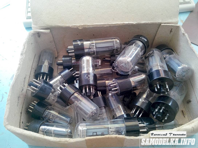
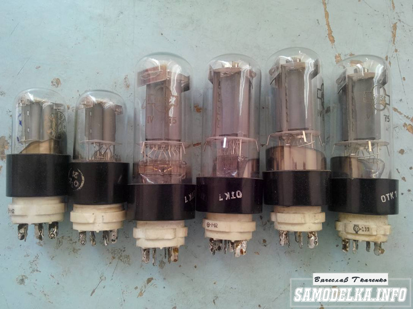
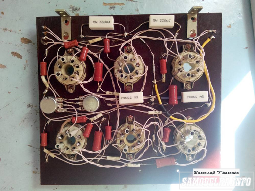
When they said that the black and white record was not working, it was not a pity to remove the lamps. I removed the lamps, capacitors (they were in good condition), a couple of resistors and three transformers - power, TVK and TV-ZSh (See Fig. 3.1, 3.2).


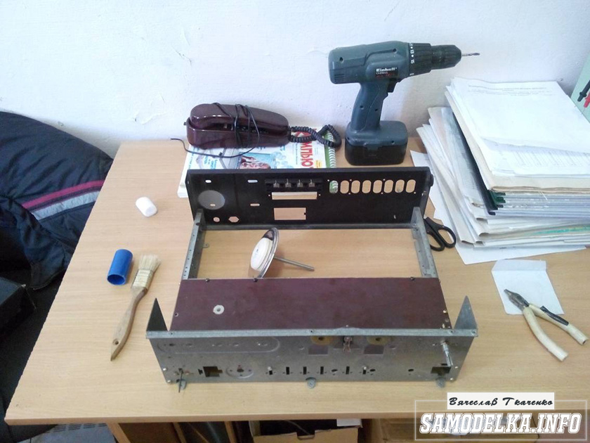
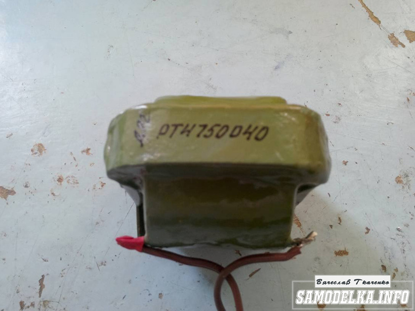
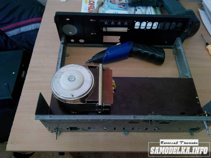
I purchased the missing elements, and again the problem arose. There was enough for the first channel, but the second needed a couple more trans units - TVK and TV-ZSh, where TVK played the role of a power choke, and TV-ZSh an output transformer. Well, I dealt with this problem and already went to extremes by buying a transformer. Meanwhile, the second month of summer is already approaching, yeah, I’ve been searching for so long. Well, then I had to work on the amplifier case, I found a power supply case from Soviet logic and decided to get creative, it didn’t turn out very well, of course, but I think it’ll do for the first time. The basis was this frame from the power supply (See Fig. 1). The bottom base was made from laminate boards, and the top cover was also made from it; for the sides I also made overlays from laminate, but this time lighter.


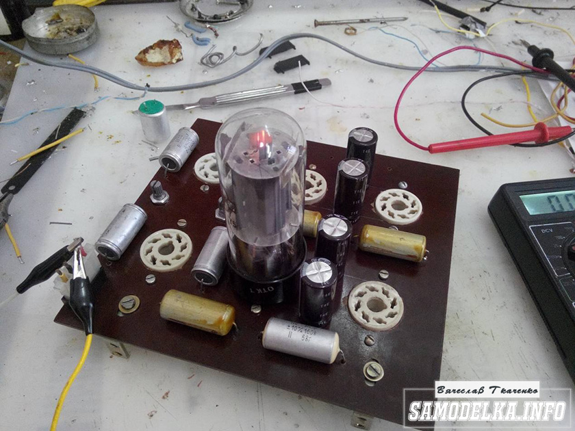
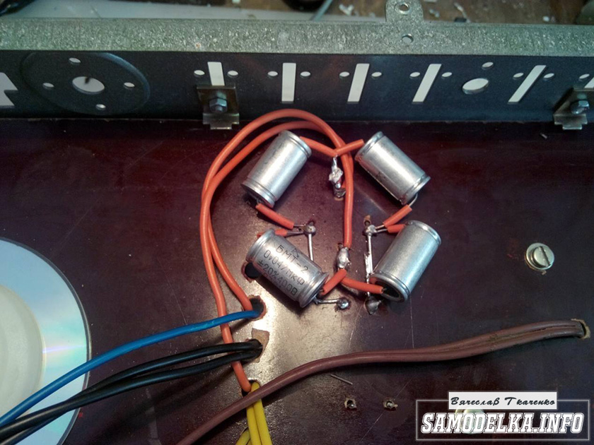
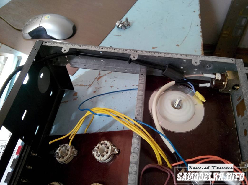
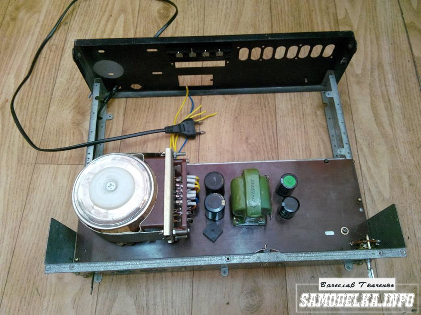
Now for the assembly: I installed the power transformer at the back, blocking it with a shutter made from the iron cover of the power supply unit (it turned out to be a kind of screen). Inside I installed a diode bridge made of her407 diodes, two anode chokes and sound transformers (See Fig. 4.1, 4.2). Next, the top board of the laminate was fitted to the body and the fresco was removed, including for the panels of lamps with condensers, which were installed on this board (See Fig. 2). Now I started installing and soldering the elements, and spread the ground. I soldered shielded Soviet wires to the input. By the way, the heat is also from Soviet wires (See the remaining photos at the bottom of the article).


— most connoisseurs of high-quality music, who know how to handle soldering equipment and have some experience in repairing radio equipment, can try to assemble a high-class tube amplifier, which is usually called Hi-End, on their own. Tube devices of this type belong in all respects to a special class of household radio-electronic equipment. Basically, they have an attractive design, with nothing covered by a casing - everything is in plain sight.
After all, it is clear that the more visible the electronic components installed on the chassis are, the greater the authority of the device. Naturally, the parametric values of a tube amplifier are significantly superior to models made with integrated or transistor elements. In addition to this, when analyzing the sound of a tube device, all attention is paid to the personal assessment of the sound rather than to the image on the oscilloscope screen. In addition, it has a small number of used parts.
How to choose a tube amplifier circuit
In case of choosing a pre-amplifier circuit there is no special problems, then when choosing a suitable final stage circuit, difficulties may arise. Tube audio power amplifier may have several versions. For example, there are single-cycle and push-pull devices, and also have different operating modes of the output path, in particular “A” or “AB”. The output stage of single-ended amplification is, by and large, a sample, because it is in mode “A”.
This operating mode is characterized by the lowest nonlinear distortion values, but its efficiency is not high. Also, the output power of such a stage is not very large. Consequently, if it is necessary to sound an internal space of medium size, a push-pull amplifier with the “AB” operating mode will be required. But when a single-cycle device can be made with only two stages, one of which is preliminary and the other amplifying, then a driver is needed for the push-pull circuit and its correct operation
But if single-cycle tube audio power amplifier may consist of only two stages - a pre-amplifier and a power amplifier, then a push-pull circuit for normal operation requires a driver or cascade that forms two voltages of identical amplitude, shifted in phase by 180. Output stages, regardless of whether it is single-ended or push-pull, require the presence of output transformer. Which plays the role matching device interelectrode resistance of a radio tube with low acoustic resistance.
True admirers of “tube” sound argue that the amplifier circuit should not have any semiconductor devices. Therefore, the power supply rectifier must be implemented using a vacuum diode, which is specially designed for high-voltage rectifiers. If you intend to repeat a working, proven tube amplifier circuit, then you do not need to immediately assemble a complicated push-pull device. To provide sound in a small room and obtain an ideal sound picture, a single-ended tube amplifier is fully sufficient. In addition, it is easier to manufacture and configure.
The principle of assembly of tube amplifiers
There are certain rules for installing radio-electronic structures, in our case these are tube audio power amplifier. Therefore, before starting the manufacture of the device, it would be advisable to thoroughly study the primary principles of assembling such systems. The main rule when assembling structures using vacuum tubes is to route the connecting conductors along the shortest possible path. The most effective method is to refrain from using wires in places where you can do without them. Fixed resistors and capacitors must be installed directly on the lamp panels. In this case, special “petals” must be used as auxiliary points. This method of assembling a radio-electronic device is called “mounted mounting”.
In practice, when creating tube amplifiers printed circuit boards do not apply. Also, one of the rules says - avoid laying conductors parallel to each other. However, such a seemingly chaotic layout is considered the norm and is completely justified. In many cases, when the amplifier is already assembled, a low-frequency hum is heard in the speakers; it must be removed. The primary task is performed by the correct choice of the ground point. There are two ways to organize grounding:
- The connection of all wires going to the “ground” at one point is called an “asterisk”
- Install an energy-efficient electrical copper bus around the perimeter of the board, and solder conductors to it.
The location for the grounding point must be verified by experiment, listening for the presence of background. To determine where the low-frequency hum comes from, you need to do this: Using a sequential experiment, starting with the double triode of the pre-amplifier, you need to short-circuit the lamp grids to ground. If the background decreases noticeably, it will become clear which lamp circuit is causing the background noise. And then, also experimentally, you need to try to eliminate this problem. There are auxiliary methods that are required to be used:
Pre-stage tubes
- Electrovacuum lamps of the preliminary stage must be covered with caps, and they, in turn, must be grounded
- Housings of trimming resistors are also subject to grounding
- Lamp filament wires need to be twisted
Tube audio power amplifier, or rather, the filament circuit of the pre-amplifier lamp can be powered with direct current. But in this case, you will have to add another rectifier assembled using diodes to the power supply. And the use of rectifier diodes in itself is undesirable, since it breaks the design principle of manufacturing a Hi-End tube amplifier without the use of semiconductors.
Placing the output and mains transformers in pairs in a lamp device is sufficient important point. These components must be installed strictly vertically, thereby reducing the background level from the network. One of them effective ways Installation of transformers is to place them in a casing made of metal and grounded. The magnetic cores of transformers also need to be grounded.
Retro components
Radio tubes are devices from ancient times, but they have become fashionable again. Therefore it is necessary to complete tube audio power amplifier with the same retro elements that were installed in the original lamp designs. If this concerns permanent resistors, then you can use carbon resistors that have high stability of parameters or wire resistors. However, these elements have a large scatter - up to 10%. Therefore, for a tube amplifier, the best choice would be to use small-sized precision resistors with a metal-dielectric conductive layer - C2-14 or C2-29. But the price of such elements is significantly high, so instead of them, MLTs are quite suitable.
Particularly zealous adherents of the retro style get an “audiophile’s dream” for their projects. These are carbon resistors BC, developed in the Soviet Union specifically for use in tube amplifiers.  If desired, they can be found in tube radios from the 50s and 60s. If according to the circuit the resistor must have a power of more than 5 W, then wirewound resistors PEV coated with glassy heat-resistant enamel.
Capacitors used in tube amplifiers are generally not critical to a particular dielectric, as well as to the design of the element itself. Any type of capacitor can be used in the tone control paths. Also, in the rectifier circuits of the power supply, you can install any type of capacitors as a filter. When designing high-quality low-frequency amplifiers, the coupling capacitors installed in the circuit are of great importance.
They have a special influence on the reproduction of a natural, undistorted sound signal. Actually, thanks to them we get exceptional “tube sound”. When choosing coupling capacitors that will be installed in tube audio power amplifier, special attention must be paid to ensure that the leakage current is as small as possible. Because the correct operation of the lamp, in particular its operating point, directly depends on this parameter.
In addition, we must not forget that the separating capacitor is connected to the anode circuit of the lamp, which means that it is under high voltage. So, such capacitors must have an operating voltage of at least 400v. One of the best capacitors working as a transition capacitor are those from JENSEN. It is these capacities that are used in top-end HI-END class amplifiers. But their price is very high, reaching up to 7,500 rubles for one capacitor. If you use domestic components, then the most suitable ones would be, for example: K73-16 or K40U-9, but in terms of quality they are significantly inferior to branded ones.
Single-ended tube audio power amplifier
The presented tube amplifier circuit consists of three separate modules:
- Pre-amplifier with tone control
- The output stage, that is, the power amplifier itself
- Power supply
The preamplifier is manufactured using a simple circuit with the ability to adjust the signal gain. It also has a pair of separate tone controls for low and high frequency. To increase the efficiency of the device, you can add an equalizer for several bands to the design of the preamplifier.
Electronic components of the preamplifier
The pre-amplifier circuit presented here is made on one half of a 6N3P double triode. Structurally, the preamplifier can be manufactured on a common frame with an output stage. In the case of a stereo version, two identical channels are naturally formed, therefore, the triode will be fully involved. Practice shows that when starting to create any design, it is best to first use a circuit board. And after setting it up, assemble it in the main building. Provided that it is assembled correctly, the preamplifier begins to operate synchronously with the supply voltage without any problems. However, at the setup stage you need to set the anode voltage of the radio tube.
The capacitor in the output circuit C7 can be used K73-16 with a rated voltage of 400v, but preferably from JENSEN, which will provide better sound quality. Tube audio power amplifier not particularly critical of electrolytic capacitors, so any type can be used, but with a voltage margin. At the setup stage, we connect a low-frequency generator to the input circuit of the pre-amplifier and apply a signal. An oscilloscope must be connected to the output.
Initially, we set the input signal range to within 10 mv. Then we determine the output voltage value and calculate the amplification factor. Using an audio signal in the range of 20 Hz - 20000 Hz at the input, you can calculate the throughput of the amplification path and display its frequency response. By selecting the capacitance value of the capacitors, it is possible to determine the acceptable proportion of high and low frequencies.
Setting up a tube amplifier
Tube audio power amplifier implemented on two octal radio tubes. A double triode with separate cathodes 6N9S connected in a parallel circuit is installed in the input circuit, and the final stage is made on a fairly powerful output beam tetrode 6P13S connected as a triode. Actually, it is the triode installed in the final path that creates exceptional sound quality.
To execute easy setup For an amplifier, an ordinary multimeter will be enough, but to make accurate and correct adjustments you need to have an oscilloscope and a generator audio frequencies. You need to start by setting the voltage at the cathodes of the 6N9S double triode, which should be within 1.3v - 1.5v. This voltage is set by selecting a constant resistor R3. The current at the output of the 6P13S beam tetrode should be in the range from 60 to 65 mA. If a powerful constant resistor 500 Ohm - 4 W (R8) is not available, then it can be assembled from a pair of two-watt MLTs with a nominal value of 1 kOhm and connected in parallel. All other resistors indicated in the diagram can be installed of any type, but preference is still given to C2-14.
Just like in the preamplifier, the important component is the decoupling capacitor C3. As mentioned above, the ideal option would be to install this element from JENSEN. Again, if you don’t have them at hand, you can also use Soviet film capacitors K73-16 or K40U-9, although they are worse than overseas ones. For correct operation of the circuit, these components are selected with the lowest leakage current. If it is impossible to carry out such a selection, it is still advisable to buy elements from foreign manufacturers.
Amplifier power supply
The power supply is assembled using a 5Ts3S direct filament kenotron, which provides rectification alternating current, fully complying with the design standards of HI-END class tube power amplifiers. If it is not possible to purchase such a kenotron, then you can install two rectifier diodes instead.
The power supply installed in the amplifier does not require any adjustment - everything is turned on. The topology of the circuit makes it possible to use any chokes with an inductance of at least 5 H. As an option: using such devices from outdated TVs. The power transformer can also be borrowed from old Soviet-made lamp equipment. If you have the skills, you can make it yourself. The transformer must consist of two windings with a voltage of 6.3v each, providing power to the amplifier radio tubes. Another winding should have an operating voltage of 5v, which is supplied to the kenotron filament circuit and the secondary one, which has a midpoint. This winding guarantees two voltages of 300v and a current of 200 mA.
Power amplifier assembly sequence
The procedure for assembling a tube audio amplifier is as follows: first, the power supply and the power amplifier itself are made. After the settings have been made and the necessary parameters have been installed, the preamplifier is connected. All parametric measurements measuring instruments should be done not on a “live” speaker system, but on its equivalent. This is in order to avoid the possibility of expensive acoustics being decommissioned. The load equivalent can be made of powerful resistors or thick nichrome wire.
Next you need to work on the housing for the tube audio amplifier. You can develop the design yourself, or borrow it from someone. The most affordable material for making the body is multilayer plywood. The output and preliminary stage lamps and transformers are installed on the upper part of the housing. On the front panel there are tone and sound control devices and a power supply indicator. You may end up with devices like the models shown here.
Briefly, mainly photos (re-uploaded to good quality). I’ll say right away that I had little experience and knowledge in radio engineering and made a lot of mistakes. Not being a fanatical lover of warm tube sound, the assembly process itself was interesting to me.
The hardest part is finding the output transformers. I bought myself ready-made ones from the TU-100M amplifier (I didn’t choose for a long time, I took what they had). The frame was made from an aluminum profile and the strength margin was a little overdone.
The upper part of the body was made of 3mm steel. Holes for transformers and lamps were laser cut. The bottom was also cut from 2mm steel with ventilation holes:
Front panel made from a piece of aluminum:
Scheme
The final amplifier is assembled using a push-pull circuit using two G-807 lamps. The preamplifier contains two amplification stages assembled on a 6N9S double triode (foreign analogue of 6SL7).Advantages of 6N9S:
1) The lamp was originally designed for audio applications;
2) Two triodes in a cylinder;
3) High linearity;
4) Wide distribution, low price.
Disadvantages of 6N9S:
1) High internal resistance.
The pre-terminal amplifier (an intermediate link between single-ended and push-pull amplifiers) is assembled using a phase-inverted circuit on a 6N9S double triode; its main purpose is to form two mutually antiphase, equal in amplitude signals from the input signal. In the TU-100M circuit, the lamp amplifies the input signal and the voltage amplified by it is supplied to the lamp grid of the first arm of the push-pull amplifier.
Part of the output voltage of the first lamp of the phase-inverted amplifier is supplied to the input of the second lamp of this amplifier. The voltage amplified by the second lamp of the phase-inverted amplifier is supplied to the grid of the lamp of the second arm of the push-pull
amplifier Thus, for the first arm of a push-pull amplifier the signal passes through one tube, and for the second through two.
It would be better if the voltage applied to the input of the first arm was equal to the voltage at the input of the second arm. I made a slightly different circuit, with a modified phase inversion stage.
Advantages:
1) Reduced requirements for supply voltage filtering;
2) Extremely low noise level;
3) Equal output voltages of the shoulders.
I found another option on the forums:

Sockets for lamps 6N9S:

The amplifier housing contains a DAC with the ability to connect to a computer via USB:


Adjustment option:

Transformer screens, first sketches on paper:

Cut from 2mm steel: 
After filing and sanding:


Some more photos:


Cleaned it up a bit:


Price: unreasonably expensive.
It’s easier to buy ready-made for 4-5 thousand rubles. But if anyone needs it, I can send you files for cutting and for printed circuit boards.
This tube amplifier is designed and built from the ground up. This is a very long project and it required a lot of time and patience from the author of this project. Let's analyze all the pros and cons of this homemade product together with the author.
IMPORTANT! This device has lethal voltage inside. If you do not know about high voltages and electronics, then it is not advisable to repeat this homemade product. Otherwise, you do this at your own peril and risk! It is not recommended to dig into the device with electronic tubes while it's on!
Step one: The idea itself

Several old lamps were found in a box at my grandparents' house. It was decided to make a low-frequency amplifier based on them. Other semiconductors were not used in principle in this homemade product. I had to do some research to figure out how these tube amps worked.
Step Two: Circuit and Components


Designing the circuit was probably the most difficult part of this project. First, a list of tubes that were available was written, and then, based on them, a drawing was drawn circuit diagram project. A push-pull stereo amplifier was designed with tone controls, phono and aux inputs and some VU meters. EL84c tubes were required and it was decided to use simple dual triodes for other stages. The lamps quickly ran out and I had to order new ones.
Then it was time for the next challenge: the output transformer. A cheap transformer was not easy to find. But after a little searching, the transformer was eventually found on a popular message board. The transformer is designated as NASS II-12 in the diagram. "NASS" stands for "Not A Single Semiconductor", II stands for push-pull and has a total of 12 legs.
Step Three: First Test


The chaos on the table above is the assembly of components in the air.
This uses two regular power transformers in series as the output transformer, just to check if everything works. Everything seemed to be in order and now it was time to find the power transformer. There was an old transformer in stock and the author attempted to wind the transformer himself. However, after disassembling, rewinding and testing, I had to give up the idea... Therefore, I took one transformer from an old radio, thinking that everything would be fine. But that's not true. But more on that later.
Step Four: Product Body


The material for the body was supposed to be aluminum. Brushed aluminum front, top and back plate. The sides are some kind of hardwood. Unfortunately, the author had to abandon the aluminum top cover because resources were limited. Front and rear end were made of three-layer material (two sheets of aluminum and one plastic between them). The top cover required a strong and durable material because it had to withstand the heat generated by the lamps and support the weight of the main transformer. Therefore, the decision was in favor of PCB. This material is brownish in color, is relatively durable and easy to work with.
Important! The entire chassis must be electrically shielded and connected to ground at only one point to avoid ground loops. In this case, spray adhesive and a thin aluminum radiator were used.
Front and back panels were designed in SolidWorks to see what the amplifier looked like. A drill press was then used to make the necessary holes for the connectors, fuses, switches, potentiometers and VU meters. Fine-grained sandpaper was used to ensure a good surface finish. Transfer foil was then used to print the labels, which was coated with a layer of shiny and clear coating to prevent the letters from rubbing off over time.
The top panel was first installed for a test fit, and then the necessary holes were drilled.
Step Five: Amplifier Wiring


To ensure that the top panel could withstand the transformers, the structure was reinforced with sheet metal. After this, the wiring began. This is the most labor-intensive procedure. First, bolts are attached to the transformers and pipes, and then the necessary components are soldered. The tone control module needed additional shielding because it picked up environmental noise. Therefore, it was installed in a metal box.
Step Six: Final Assembly, Issues and Specifications


Thus, everything was collected. After the test it turned out that the main power transformer There were problems with very high current, it got very hot. After about 30 minutes it reached temperatures of over 90 C. This was above its optimal operating temperature. Even after installing a small fan inside the case, it was not possible to reduce the temperature. Therefore, I had to install another 6.3V transformer inside the case. This solved the problem of high temperature of the main transformer.
Another problem was very high level noise. This is likely due to ground loops that were accidentally left in the circuit.
Therefore, modernization of this amplifier is inevitable.
At the end of the day, despite this amp's minor shortcomings, this author says it sounds great!
This amplifier can deliver 15 watts RMS per channel without any noticeable distortion. It consumes about 10-15 W from the network when idling and about 100 W when the transformers are running at full power.
Today we have a useful homemade product for connoisseurs of good sound: a high-quality tube amplifier made by yourself
Hello!
I decided to assemble a push-pull tube amplifier (my hands were really itching) from the parts I had accumulated over a long time: housing, lamps, sockets for them, transformers, etc.
I must say that I got all this stuff for free (you mean free of charge) and the cost of my new project will be 0.00 hryvnia, and if I need to buy something in addition, I’ll buy it for rubles (since I started my project in Ukraine, and I’ll finish already in Russia).
I'll start the description with the body.

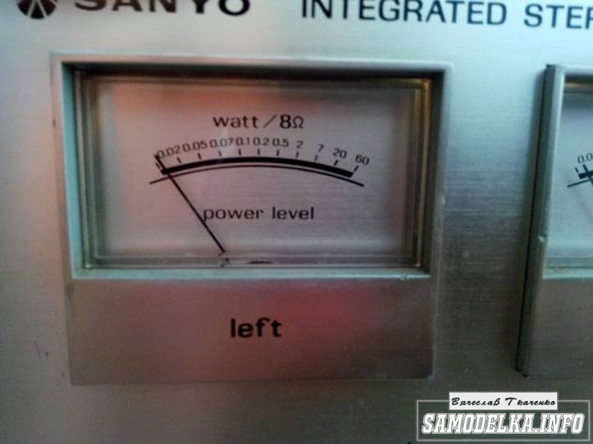
Once upon a time it was, apparently, a good amplifier from SANYO model DCA 411.
But I didn’t have a chance to listen to it because I got it in a terribly dirty and non-working state, it was dug up beyond repair and the burnt 110 V power supply (Japanese, probably) smoked all the insides. Instead of the original final stage microcircuits, there are some snot from Soviet transistors (this is a photo from the Internet of a good example). In short, I gutted it all out and began to think. So, I couldn’t think of anything better than stuffing a lamp there (there’s quite a lot of space there).
Decision is made. Now we need to decide on the scheme and details. I have a sufficient number of 6p3s and 6n9s lamps.

Due to the fact that I had already assembled a single-cycle amplifier for 6p3s, I wanted more power and, having rummaged through the Internet, I chose this push-pull amplifier circuit for 6p3s.
Circuit of a homemade tube amplifier (ULF)

The diagram is taken from the website heavil.ru
I must say that the scheme is probably not the best, but due to its relative simplicity and availability of parts, I decided to stick with it. Output transformer (an important figure in the plot).
It was decided to use the “legendary” TS-180 as output transformers. Don’t throw stones right away (save them for the end of the article :)) I myself have deep doubts about this decision, but given my desire not to spend a penny on this project, I will continue.

I connected the trance outputs for my case like this.
(8)—(7)(6)—(5)(2)—(1)(1′)—(2′)(5′)—(6′)(7′)—(8′) primary
(10)—(9)(9′)—(10′) secondary
anode voltage is applied to the connection of pins 1 and 1′, 8 and 8′ to the anodes of the lamps.
10 and 10′ per speaker. (I didn’t come up with this myself, I found it on the Internet). To dispel the fog of pessimism, I decided to check the frequency response of the transformer by eye. To do this, I quickly assembled such a stand.

In the photo there is a GZ-102 generator, a BEAG APT-100 amplifier (100V-100W), an S1-65 oscilloscope, a 4 Ohm load equivalent (100W), and the transformer itself. By the way, there is a .
I set it to 1000 Hz with a swing of 80 (approximately) volts and record the voltage on the oscilloscope screen (about 2 V). Next, I increase the frequency and wait until the voltage on the trance secondary starts to drop. I do the same thing in the direction of decreasing the frequency.
The result, I must say, pleased me: the frequency response is almost linear in the range from 30 Hz to 16 kHz, well, I thought it would be much worse. By the way, the BEAG APT-100 amplifier has a step-up transformer at the output and its frequency response may also not be ideal.
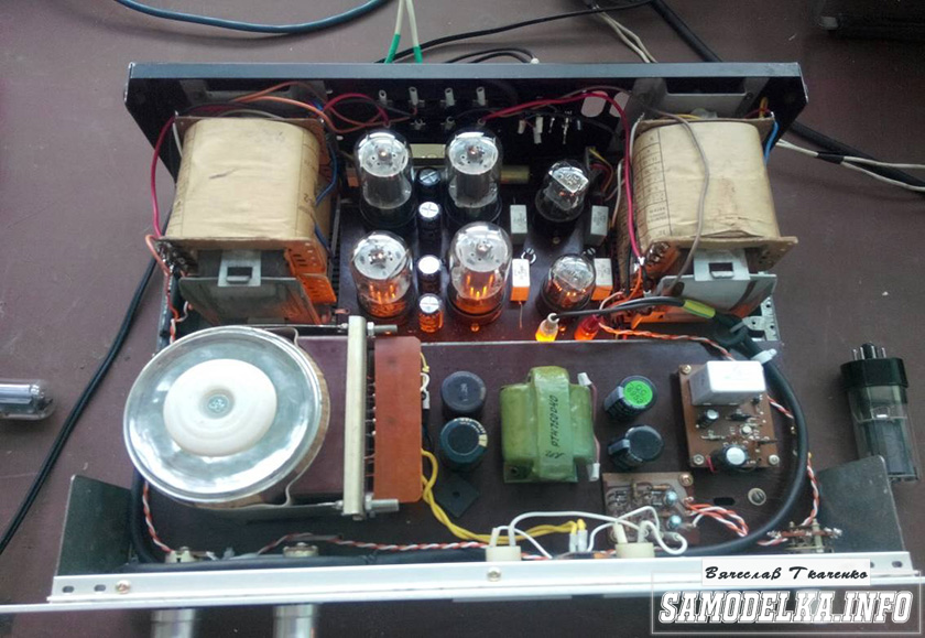
Now you can collect everything in a heap into a case with a clear conscience. There is an idea to do the installation and layout inside in the best traditions of so-called modding (minimum wires in sight) and it would also be nice to have LED backlighting like in industrial copies.
Power supply for a homemade tube amplifier.
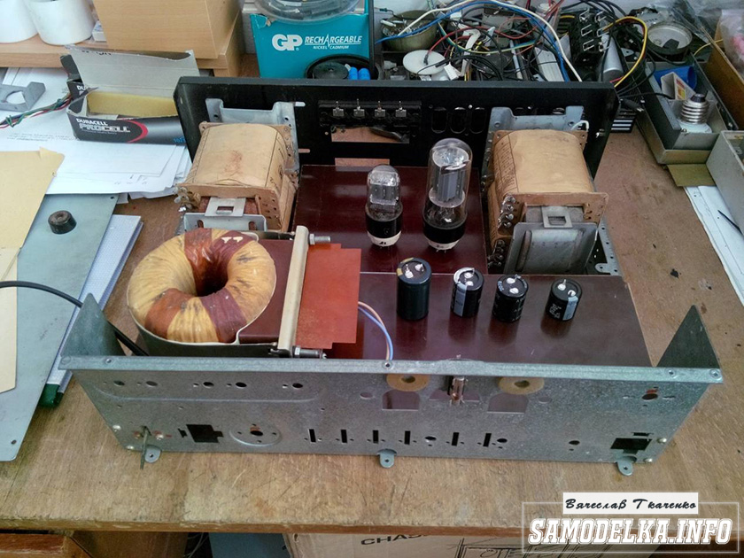
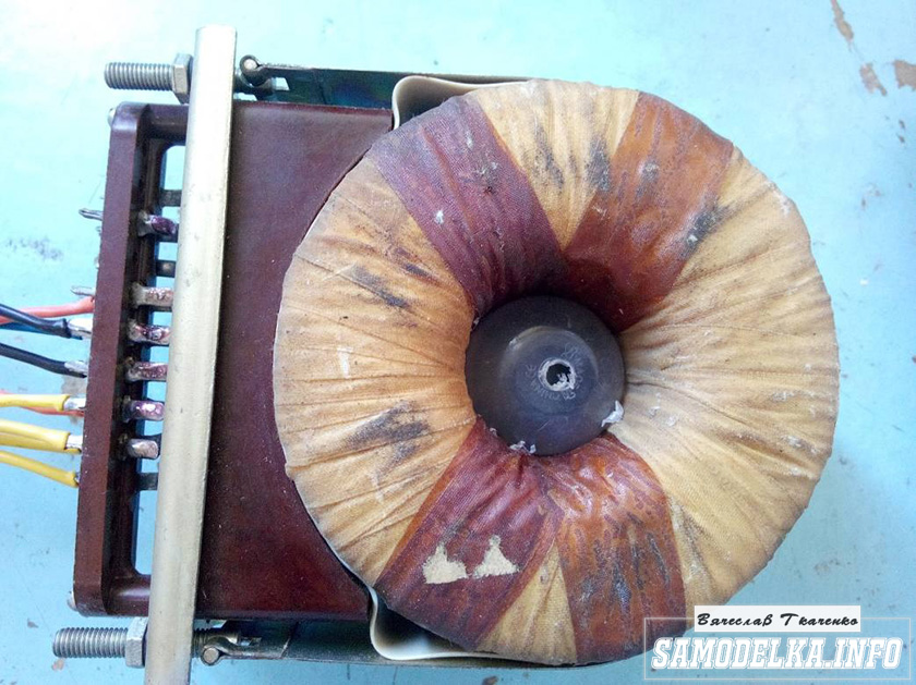
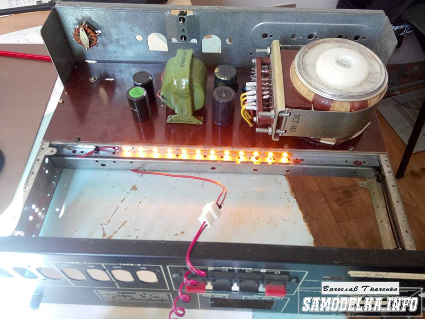
I'll start the assembly and at the same time describe it. The heart of the power supply (and of the entire amplifier, probably) will be the TST-143 toroidal transformer, which I once (4 years ago) tore out of some tube generator right as it was being taken to a landfill. Unfortunately, I didn’t manage to do anything else. It’s a pity for such a generator, but maybe it was still working or could have been repaired... Okay, I digress. Here he is my security officer.


Of course, I found a diagram for it on the Internet.

The rectifier will be on a diode bridge with a filter on the inductor for anode power. And 12 volts to power the backlight and anode voltage. This is the throttle I have.
Its inductance was 5 henry (according to the device), which is quite enough for good filtration. And the diode bridge was found like this.
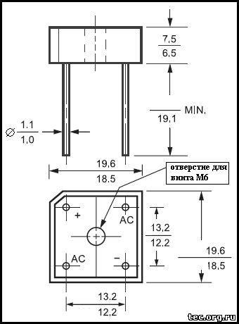
Its name is BR1010. (10 amps 1000 volts). I'm starting to cut out the amplifier. I think it will be something like this.
I mark and cut holes in the PCB for the sockets for the light bulbs.

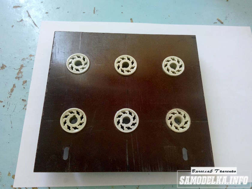


It turns out well :) I like everything so far.

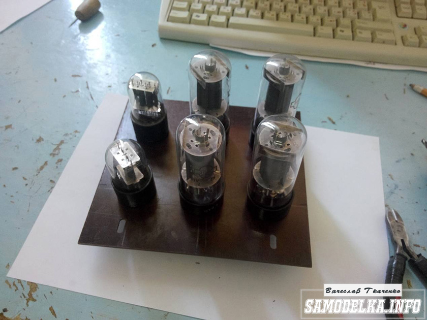
This way and that way. drill and saw :)


Something began to emerge.

I found a fluoroplastic wire in old supplies and immediately all the alternatives and compromises regarding the wire for installation disappeared without a trace :) .


This is how the installation turned out. Everything seems to be “kosher”, the incandescence is intertwined, the ground is practically at one point. Should work.
It's time to fence in food. After checking and testing all the output windings of the trans, I soldered all the necessary wires to it and began installing it according to the accepted plan.

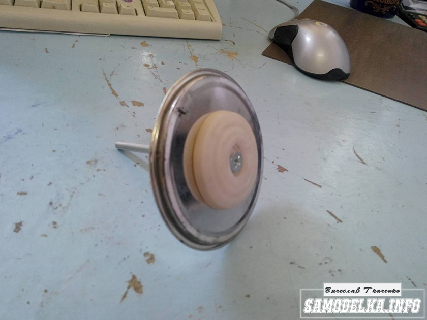
As you know, in our life it’s not easy to go anywhere without improvised materials: this is how the Kinder Surprise container came in handy.
And a Nescafe lid and an old CD


I tore out the circuit boards of TVs and monitors. All containers are at least 400 volts (I know that I should have more, but I don’t want to buy them).
I bridge the bridge with containers (whatever were on hand, I’ll probably change them later)

It’s a bit much, but oh well, it will sag under load :)
I use the standard power switch from the amplifier (clear and soft).
We're done with that. It turned out well :)
Backlight for tube amplifier housing.
To implement the backlight, an LED strip was purchased.

And installed in the housing as follows.

Now the glow of the amplifier will be visible during the daytime. To power the backlight, I will make a separate rectifier with a stabilizer on some KRKEN-like microcircuit (which I can find in the trash), from which I plan to power the anode voltage supply delay circuit.
Delay relay.
Having rummaged through the bins of my homeland, I found this completely untouched thing.

This is a radio time relay designer for a photo enlarger.


We collect, check, try on.
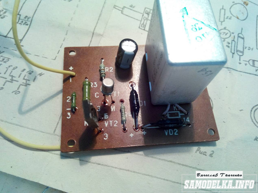
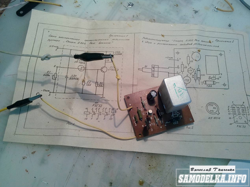

I set the response time to about 40 seconds, and replaced the variable resistor with a constant one. The matter is coming to an end. All that remains is to put everything together, install the face, indicators and regulators.
Regulators (input variables)
They say the sound quality can greatly depend on them. In short, I installed these
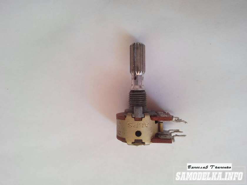
Dual 100 kOhm. Since I have two of them, I decided to parallel the pins, thereby obtaining 50 kOhm and increased resistance to wheezing :)
Indicators.
I used standard indicators, with standard backlighting
I mercilessly copied the connection diagram from the original board and used it as well.
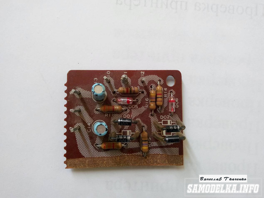
This is what I ended up with.


When checking the power, the amplifier demonstrated an output voltage of 10 volts of an undistorted sine wave with a frequency of 1000 Hz into a 4 ohm load (25 watts) equally across channels, which was pleasing :)
When listening, the sound was crystal clear without background and dust, as they say, but too monitory, or what? beautiful, but flat.
I naively believed that he would play without timbres, but...
Using a software equalizer, we managed to get a very beautiful sound that everyone liked. Thank you all very much!!!
Author of the article “homemade tube amplifier with your own hands” Vyacheslav Tkachenko.
You may be interested in the following materials.
Publications on the topic
-
 Note: negative offset
Using the BGCOLOR attribute, you can change the color of the contents of a cell, a row, a group of columns, a group of rows, or an entire table. Color can...
-
 How to put a password on a folder, file or flash drive
When you try to protect personal data, you probably set a password to boot the system or create an account with...